TM049 27L Continuous Flow Service Instructions
REV AL – Issued April 2019
This document is stored and maintained electronically by Rheem Technical Support. All printed copies are deemed “uncontrolled”.
Fault Finding Tests 26 - 29
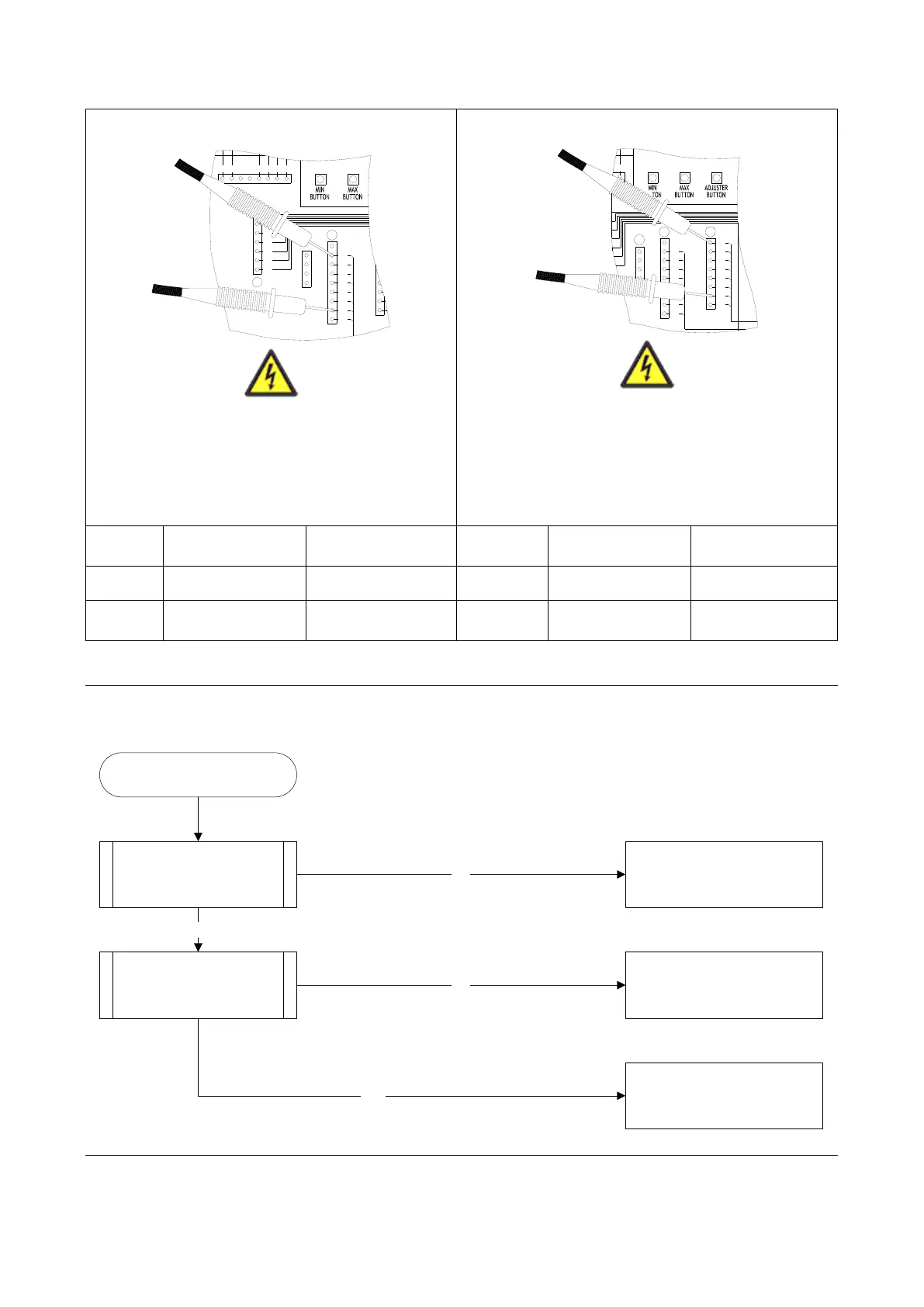
Conduct test with water flowing
Using a multimeter set on the DC volts scale,
measure the voltage at connector N whilst
plugged into PCB.
Conduct test with water flowing
Using a multimeter set on the DC volts scale,
measure the voltage at connector M whilst
plugged into PCB.
Error Code 71
Gas Inlet Solenoid Valve (GISV) fault.
Error Code 71
Check wiring, if intact replace the
control PCB.
NO
Is there voltage at the GISV?
TEST 9
Replace the gas valve assembly.YES
Is multi-pin plug fully inserted
into terminal W on control
PCB?
YES
Ensure multi-pin plug is fully
inserted.
NO
Error Code 72
Follow the same procedure as used in Error Code 51.
BK R YBR G W
4 5 6 87
R
BK
BK
R
4
2
6
5
P
Y
1
2
3
4
BL
O
W
BR
R
BK
4
3
1
8
7
6
5
N
9
Y
G
5
6
1
2
3
4
SW1 SW2
1
3
SW3SW2SW1
BL
O
W
BR
R
BK
Y
G
4
3
1
8
7
6
5
M
G
Y
9
O
N
6
7
8
1
2
BK
R
BR
W
4
3
2
W
 Loading...