31
7.0 COMPONENTS & CONTROLS
7.5 EcoNet
TM
2-Stage Outdoor Control (TSODC) (cont.)
• C- 24VAC Common from the indoor unit 24VAC
transformer
• E- 1 Data: System Communications Line 1
• E- 2 Data: System Communications Line 2
Low Volt Fuse
• If required replace with 3 A automotive ATC style
blade fuse
Low Pressure Control (LPC Input)
• Low-pressure control is factory installed
• Low-pressure control is an automatic resetting device
High Pressure Control (LPC Input)
• High-pressure control is factory installed
• High-pressure control is an automatic resetting device
Ambient Temperature Sensor
(included with all applications)
• Included with all applications
Up and Select Buttons
• Up and Select buttons used to enter Test and Fault
Recall Mode
Memory Card
• The memory card stores all unit information.
• The unit information is called model data.
• The shared data is all the information needed for
proper unit operation.
7.5.2 Overview of TSODC
Operation
Installation Verication
• 24V AC power must be present at the R and C termi-
nals on the control board for it to operate
• Line voltage must be present at the control for the
compressor and the outdoor fan to operate.
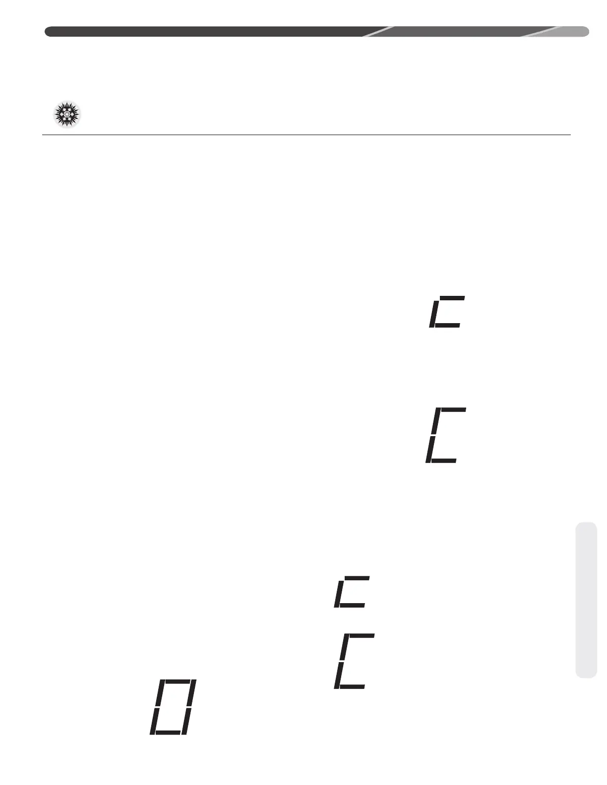
• The 7 segment LED displays a “0” for standby mode.
Standby mode indicates line voltage and 24VAC are
present at the control and there is not a command for
unit operation from the EcoNet
TM
Control Center or
Thermostat.
Zero (0) displayed
The unit is in standby
Command for Compressor Operation
• The control has an on/off fan delay of one (1) second
for each stage of cooling.
• The control ignores the low pressure control for the
rst 90 seconds of compressor operation.
• The dual 7-segment LED displays ve (5) operational
status codes.
1) First Stage Cooling Operation
When the control received a command for rst
stage cooling operation, a low case “c” is displayed
on the dual 7-segment LEDs.
Low case “c” indicates rst stage cooling operation
2) Second Stage Cooling Operation
When the control received a command for second
stage cooling operation, a upper case “C” is dis-
played on the dual 7-segment LEDs.
Upper case “C” indicates second stage cooling operation
5-minute Anti-Short Cycle Timer
• The control has a built in 5-minute time delay
between cooling cycles to protect the compressor
against short cycling. The 7-segment LED will ash
“c” or “C” while the short cycle timer is active and a
command for unit operation is received.
Flashing low case c
A command for rst stage cooling has been received
Flashing upper case C
A command for second stage cooling has been received
• The 5-minutes time delay can be bypassed when
a command for compressor operation is present by
pressing the UP button. The compressor will begin
operation and the 7-segment LED will stop ashing.
EcoNet Enabled 2-Stage Control
TM
 Loading...