32
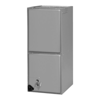
6. Remove the 3 sheet metal screws which attached the blower to the blower shelf
located in the air handler control box. (3/8” Socket)
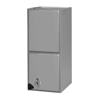
7. Lower the blower and remove from air handler.
14.8 LARGE CABINET BLOWER ASSEMBLY REMOVAL PROCEDURE
14.7 (RHAL-FR30, RHAL-FR36, AND RHBL-FR36)
1. Disconnect all power to the air handler.
2. Disconnect all blower motor leads from the control board, capacitor, and speed tap.
Reference wiring diagram for more detail.
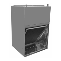
3. If equipped with a heater kit, remove the 3 screws which attach the breaker/terminal
block assembly to the blower shelf. This will help gain access to the screws in step
8. (1/4” Socket)
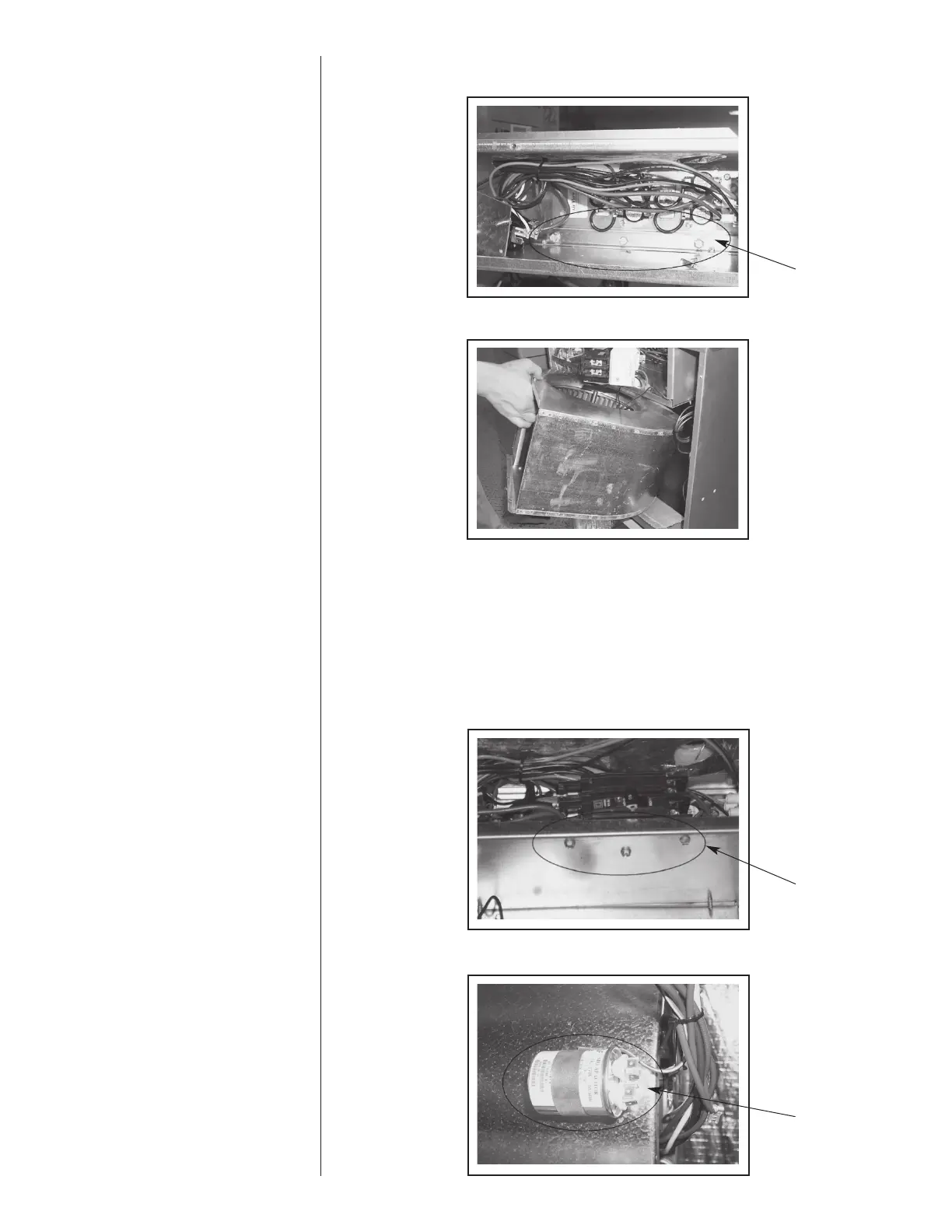
4. Remove capacitor to help prevent damage to the coil. (1/4” Socket)
Remove Screws
Remove Screws
Remove
Capacitor
 Loading...