17
INSTALLATION
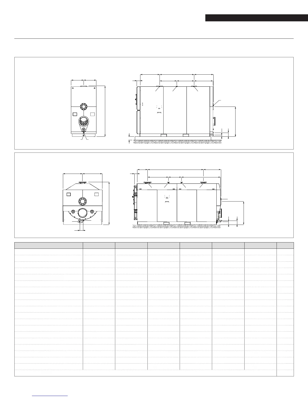
2.5 Water connections
The following table gives the dimensions and positions of the water ttings on RTC boilers.
Before installing the boiler, ush out all the pipes of the central heating circuit to remove any machining residues.
RTC 3000-RTC 4000-RTC 5000-RTC 6000
M M
L
56
N
4”
EDC
H
I
3
1 4 2
RTC 8000-RTC 10000
M M
L
6
5
N
EDC
3
44 21
H
I
DESCRIPTION RTC 3000 RTC 4000 RTC 5000 RTC 6000 RTC 8000 RTC 10000
1 - Central heating supply 4" #150 6" #150 6" #150 6" #150 8" #150 8" #150 Ø / DN
2 - HT return 3" #150 3" #150 4" #150 4" #150 6" #150 6" #150 Ø / DN
3 - LT return 4" #150 6" #150 6" #150 6" #150 8" #150 8" #150 Ø / DN
4 - Safety valve drain 2" NPT 2" NPT 2" NPT 2" NPT 2" NPT 2" NPT Ø / DN
5 - Condensate drain 1 1/4" NPT 1 1/4" NPT 1 1/4" NPT 1 1/4" NPT 1 1/4" NPT 1 1/4" NPT Ø / DN
6 - Boiler drain 1 1/2" NPT 1 1/2" NPT 1 1/2" NPT 1 1/2" NPT 1 1/2" NPT 1 1/2" NPT Ø / DN
A 25.2 25.2 33.1 33.1 19.3 19.4 inch
B 50.4 59.8 59 66.9 100.4 114.2 inch
C 18.9 28.3 29.5 29.5 37.6 47.2 inch
D 31.5 31.5 29.5 37.4 23.4 25.6 inch
E 31.3 31.2 32.5 32.5 39.4 41.3 inch
F 30.4 30.3 33.1 33.1 31.4 34.4 inch
G 46.9 48.7 51.5 54.7 41.7 45.3 inch
H 7.0 6.7 6.6 8.8 7.0 6.7 inch
I 2.5 2.4 2.6 3.3 5.5 4.5 inch
L 79.1 82.9 86.8 92.2 76.8 81.5 inch
M 19.7 20.7 21.7 23.0 35.4 37.4 inch
N 7.3 6.9 6.7 67 5.4 5.4 inch
O - - - - 5.6 5.4 inch
Flange as per ASME B16.5
 Loading...