Chapter 2 To Set the Vertical System RIGOL
MSO7000/DS7000 User Guide 2-7
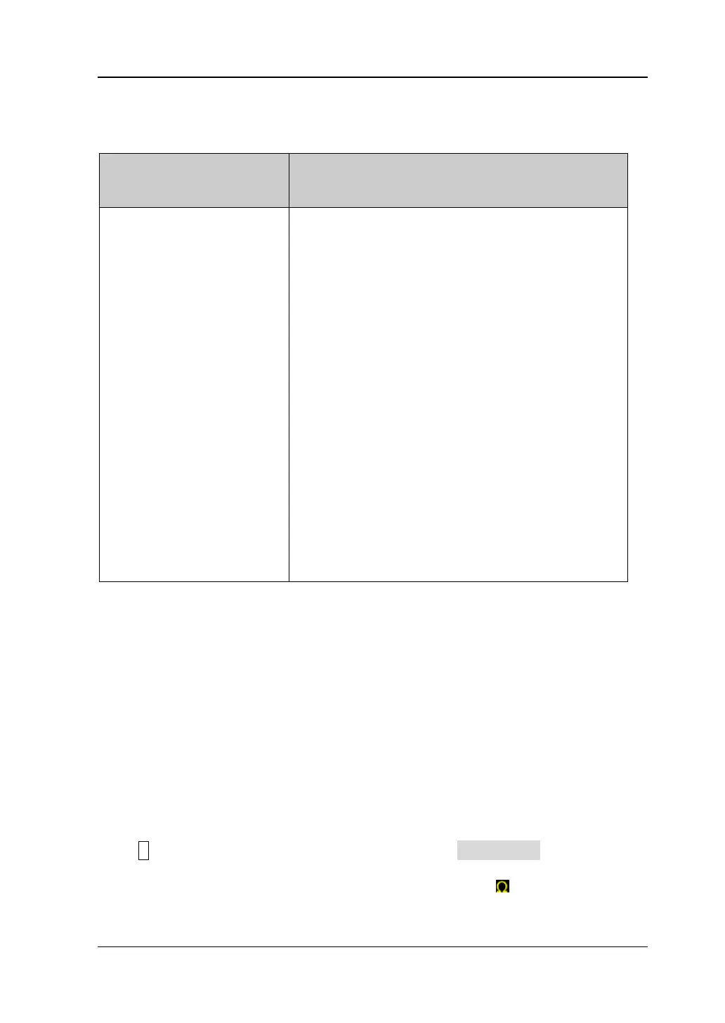
probe ratio. The probe ratio values available are as shown in Table 2-2.
Table 2-2 Probe Ratio
Attenuation Ratio
(display amplitude of the signal: actual amplitude
of the signal)
0.01X
0.02X
0.05X
0.1X
0.2X
0.5X
1X (default)
2X
5X
10X
20X
50X
100X
200X
500X
1000X
2000X
5000X
10000X
20000X
50000X
0.01:1
0.02:1
0.05:1
0.1:1
0.2:1
0.5:1
1:1
2:1
5:1
10:1
20:1
50:1
100:1
200:1
500:1
1000:1
2000:1
5000:1
10000:1
20000:1
50000:1
Note: After the oscilloscope auto-recognized certain probes with a fixed attenuation
ratio, the probe ratio will also be auto recognized. You do not have to set it
manually.
Input Impedance
To reduce the circuit load between the oscilloscope and the circuit under test, this
oscilloscope provides two input impedance modes: 1 MΩ (default) and 50 Ω.
1 MΩ: The input impedance of the oscilloscope is very high, and the current
flowed from the circuit under test can be ignored.
50 Ω: makes the oscilloscope match with the device whose input impedance is
50 Ω.
Press 1 to open the setting menu of CH1. Then, press Impedance continuously to
select the input impedance of the oscilloscope. If you select "50 Ω", the channel
status label at the bottom of the screen will display the icon .
 Loading...