Chapter 2 Performance Verification Test RIGOL
DSA1000A/DSA1000 Performance Verification Guide
Second Harmonic Distortion Test
Specification
Model DSA1030A DSA1030
Specification 35 dBm 35 dBm
Test Devices
1. Signal Generator × 1
2. 1 GHz Low-pass Filter × 1
3. Dual-BNC Cable × 1
4. N-SMA Cable × 2
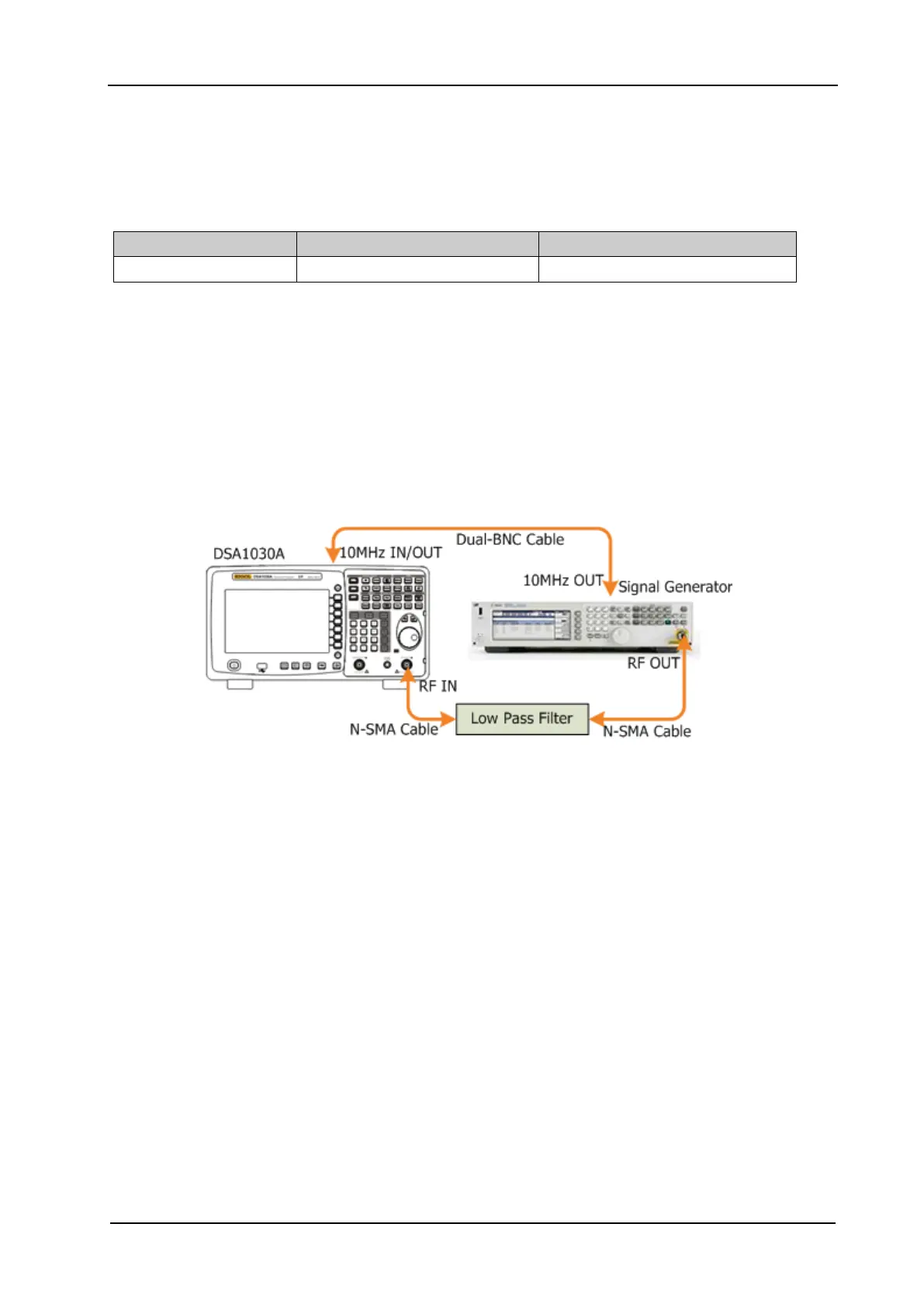
Test Connection Diagram
Figure 2-5 Second Harmonic Distortion Test Connection Diagram
Test Procedures
1. Synchronize the signal generator and spectrum analyzer. Connect the output terminal of the
signal generator with the 1 GHz low-pass filter and connect the filter with the RF input terminal
of the spectrum analyzer.
2. Set the output frequency of the signal generator to 1 GHz and the amplitude to -10 dBm.
3. Configure the spectrum analyzer:
a) Set the center frequency to 1 GHz.
b) Set the span to 10 kHz.
c) Set the reference level to -10 dBm.
d) Set the input attenuation to 10 dB.
e) Set the resolution bandwidth to 30 Hz.
f) Set the video bandwidth to 10 Hz.
g) Set the sweep time to auto and the auto sweep time to accuracy.
 Loading...