RIGOL Chapter 2 Performance Verification Test
DSA1000A/DSA1000 Performance Verification Guide
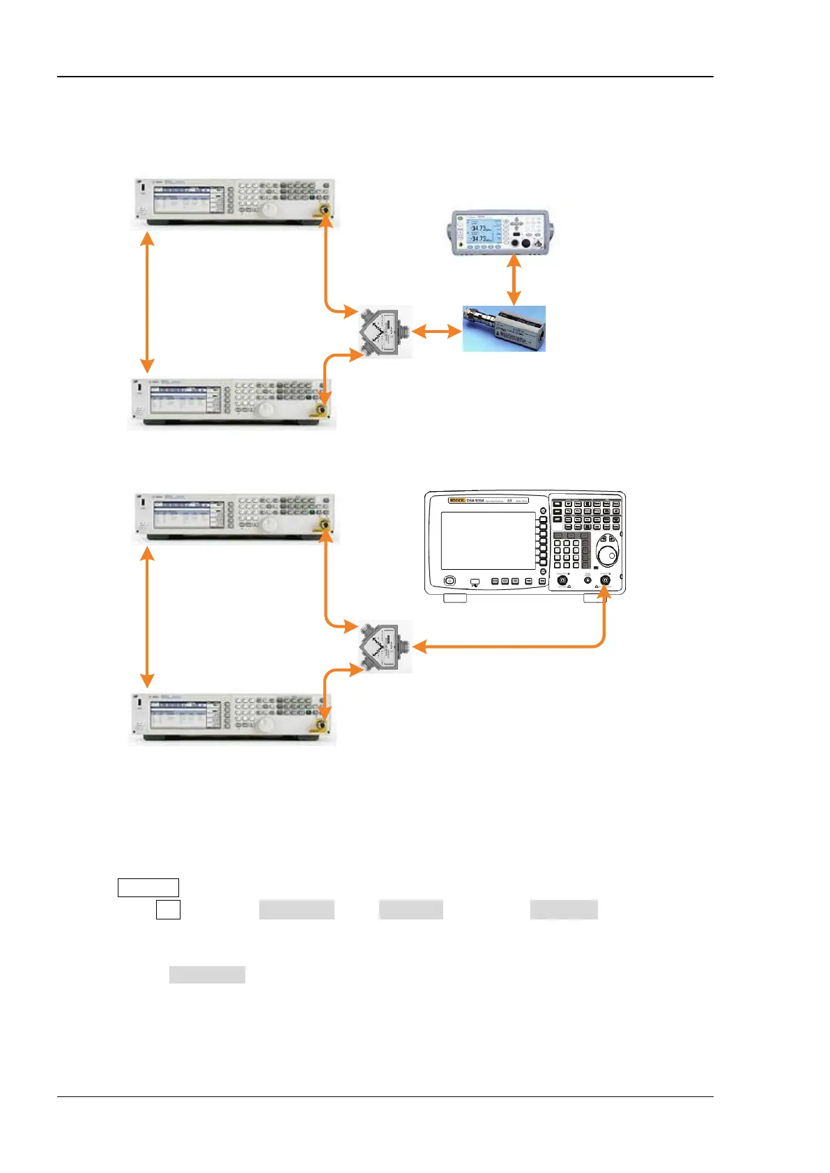
Test Connection Diagram
Signal Generator B
Signal Generator A
(a)
(b)
REF IN
10MHz OUT
Dual-BNC Cable
RF OUT
RF OUT
Dual-N Cable
Dual-N Cable
Power Divider
Power Meter
Power Sensor
Power Meter
Connecting Cable
Signal Generator B
Signal Generator A
REF IN
10MHz OUT
Dual-BNC Cable
RF OUT
RF OUT
Dual-N Cable
Dual-N Cable
Power Divider
Dual-N Cable
DSA1030A
RF IN
Figure 2-7 1 dB Gain Compression Test Connection Diagram
Test Procedures
1. Calibrate the power meter:
a) Connect the power sensor with the [REF] terminal and channel A of the power meter. Press
Channel and set the frequency of channel A to 50 MHz.
b) Press Cal and enable Power Ref in the Zero/Cal menu. Press Zero+Cal and wait for the
calibration to finish; then, observe whether the measurement value of the power meter is a
0 dBm, 50 MHz signal.
c) Disable Power Ref.
2. Synchronize the two signal generators. Connect the outputs of the two signal generators using
the power divider and connect the power divider with the power sensor, as shown in Figure 2-7
(a).
 Loading...