Value Series Manual 21
Installaon of Temperature Controller
Controller Locaon
Cable Lengths and Sizes
The controller should be out of reach of small
children.
Avoid locaons where the controller may become
hot (near the oven or radiant heater).
Avoid locaons in direct sunlight. The digital
display may be dicult to read in direct sunlight.
Avoid locaons where the temperature controller
could be splashed with liquids.
Do not install in locaons where it can be
adjusted by the public.
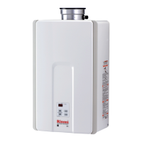
Indoor models have their controller built into the
front panel. Addional controllers can be installed.
The cable for the temperature controller should be a
non-polarized two-core cable with a minimum gauge
of 22 AWG. The maximum cable length from each
controller to the water heater depends on the total
number of wired controllers connected to the water
heater.
Number of Wired Maximum Cable Length for each
1 328 (100 m)
2 164 (50 m)
3 or 4* 65 (20 m)
Turn the power o. Do not aempt to connect the
temperature controllers with the power on. Although
the controller is a low voltage device, there is 120 volt
potenal next to the temperature controller
connecons inside the unit.
Do not connect the temperature controller to the
120VAC terminals provided for the oponal solenoid
drain valves.
WARNING
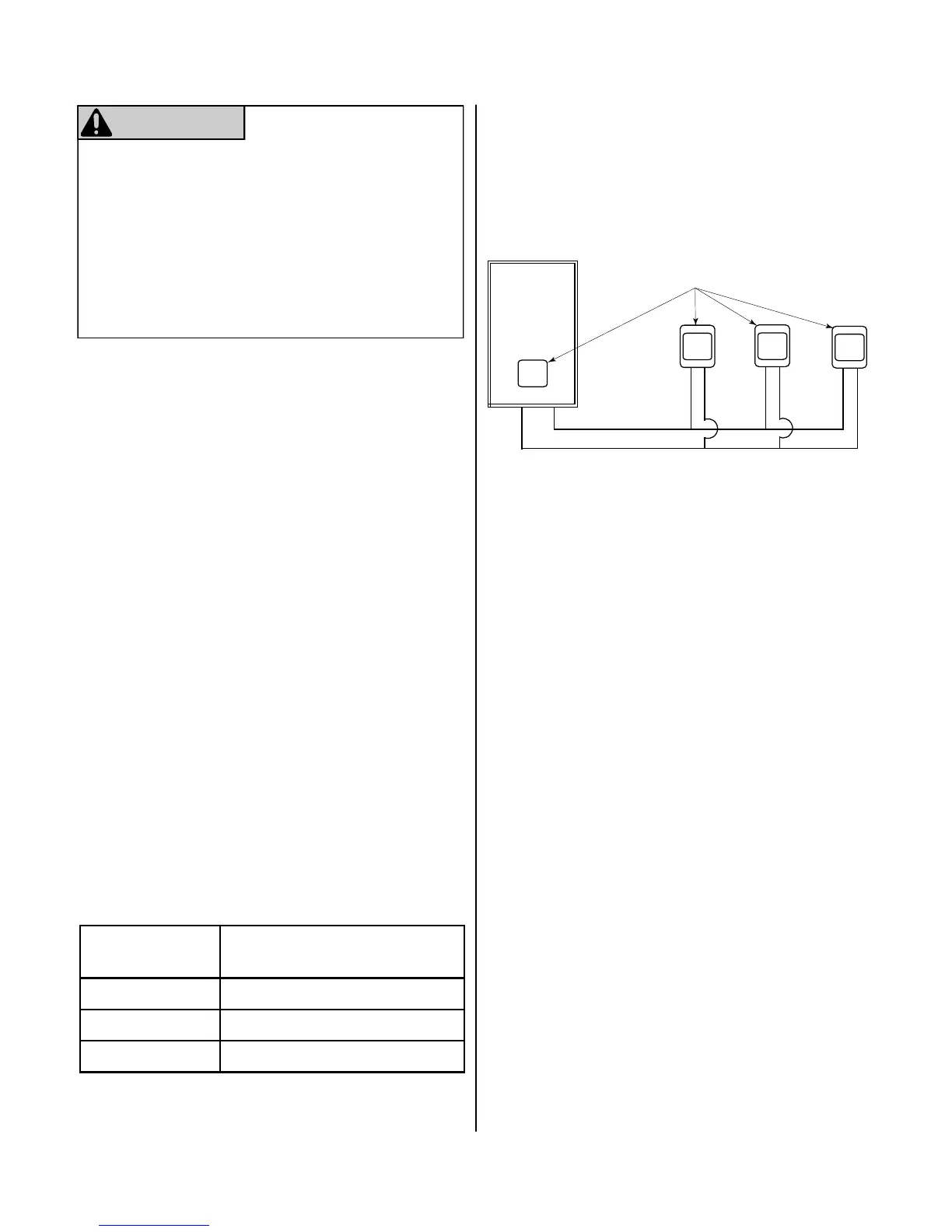
Conguraons
A maximum of 4 temperature controllers can be
installed for a water heater or bank of water heaters.
This includes the controller built into an indoor water
heater. Controllers can only be wired in parallel.
Controllers cannot be wired in series.
The 4 temperature controllers can consist of mulple
MC-91-2 or MCC-91-2 but only one BC-100V and only
one MC-100V.
The clock funcon on the BC-100V will only be
available if an MC-100V is also connected.
If 4 MC-91-2’s are installed, simultaneously press the
Priority and On/O buons on the fourth controller
unl a beep sounds.
Wire controllers in parallel
Maximum 4 Controllers
Rinnai
Water
Heater
* Only 3 addional controllers can be wired to the
indoor water heater.
 Loading...