CONN-
ECTOR
BARRIER FOLD
7514
OPEN L/S
CLOSE L/S
SPARE UNIT
SPARE UNIT
UNUSED
TOGGLE
ACTIVATION
ACTIVATION
UNUSED
UNUSED
UNUSED
UNUSED
FLASHING LAMP OUT
UNUSED
DC POWER OUT
RESET INPUT (X12)
UNUSED
DC COMMON INPUT
DC POWER INPUT
24VAC INPUT
24VAC COMMON (N)
OPEN/CLOSE COM
CLOSE OUTPUT (K1)
OPEN OUTPUT (K0)
LOOP INPUT 2
LOOP INPUT 1
DC POWER OUT
DC COMMON OUT
DC POWER OUT
LOOP INPUT (X13)
i-COMM™ CONTROLLER
Pub. No. RHSPI388 JANUARY 2006 5
i-COMM DIGITAL CONTROLLER INSTRUCTIONS
MODEL
INPUTS
X0
X1
X2
X3
X4
X5
X6
X7
X8
X9
X10
X11
PIN #
1
2
3
4
1
2
3
4
5
6
7
8
1
2
3
4
5
6
PROTECDOR
8000/CL/XL
OPEN L/S
CLOSE L/S
PRO-FAULT
SPARE UNIT
SPARE UNIT
TOGGLE
ACTIVATION
ACTIVATION
I-ZONE 1
I-ZONE 2
INT. PHOTOEYE
EXT. PHOTOEYE
FLASHING LAMP OUT
I-ZONE ALARM OUT
DC POWER OUT
RESET INPUT (X12)
UNUSED
DC COMMON INPUT
DC POWER INPUT
24VAC INPUT
24VAC COMMON (N)
OPEN/CLOSE CO
CLOSE OUTPUT (K1)
OPEN OUTPUT (K0)
LOOP INPUT 2
LOOP INPUT 1
DC POWER OUT
DC COMMON OUT
DC POWER OUT
LOOP INPUT (X13)
TRAKLINE
8910/20/PL
OPEN L/S
CLOSE L/S
SPARE UNIT
SPARE UNIT
SPARE UNIT
TOGGLE
ACTIVATION
ACTIVATION
I-ZONE 1
I-ZONE 2
INT. PHOTOEYE
EXT. PHOTOEYE
UNUSED OUTPUT
I-ZONE ALARM OUT
DC POWER OUT
RESET INPUT (X12)
UNUSED
DC COMMON INPUT
DC POWER INPUT
24VAC INPUT
24VAC COMMON (N)
OPEN/CLOSE COM
CLOSE OUTPUT (K1)
OPEN OUTPUT (K0)
LOOP INPUT 2
LOOP INPUT 1
DC POWER OUT
DC COMMON OUT
DC POWER OUT
LOOP INPUT (X13)
ISO-TEK
8600
OPEN L/S
CLOSE L/S
SPARE UNIT
SPARE UNIT
APPR. OPEN L/S
TOGGLE
ACTIVATION
ACTIVATION
I-ZONE 1
I-ZONE 2
INT. PHOTOEYE
EXT. PHOTOEYE
FLASHING LAMP OUT
UNUSED
DC POWER OUT
RESET INPUT (X12)
UNUSED
DC COMMON INPUT
DC POWER INPUT
24VAC INPUT
24VAC COMMON (N)
OPEN/CLOSE COM
INVERTER OUT 2(K1)
INVERTER OUT 1 (K0)
LOOP INPUT 2
LOOP INPUT 1
DC POWER OUT
DC COMMON OUT
DC POWER OUT
LOOP INPUT (X13)
BARRIER GLIDER
7100
OPEN L/S
CLOSE L/S
SPARE UNIT
SPARE UNIT
UNUSED
TOGGLE
ACTIVATION
ACTIVATION
UNDEDICATED
UNUSED
REVERSE
UNUSED
FLASHING LAMP OUT
UNUSED
DC POWER OUT
RESET INPUT (X12)
UNUSED
DC COMMON INPUT
DC POWER INPUT
UNUSED
UNUSED
OPEN/CLOSE COM
CLOSE OUTPUT (K1)
OPEN OUTPUT (K0)
LOOP INPUT 2
LOOP INPUT 1
DC POWER OUT
DC COMMON OUT
DC POWER OUT
LOOP INPUT (X13)
J3
J4
J5
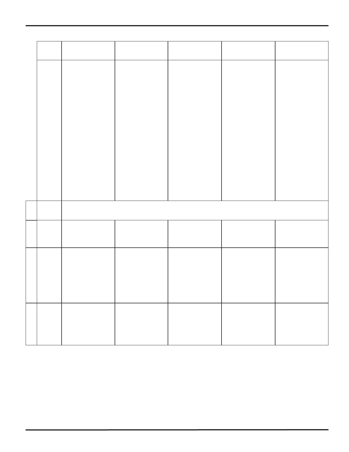
CONNECTOR TABLE
This table shows the function of each of the connectors on the i-COMM controller. The voltages listed for each pin
assume that either the input or output is activated.
NOTE: This equipment has been tested and found to comply with the limits for a Class A digital device, pursuant to Part 15 of the FCC Rules. These
limits are designed to provide reasonable protection against harmful interference when the equipment is operated in a commercial environment. This
equipment generates, uses, and can radiate
radio frequency energy and, if not installed and used in accordance with the instruction manual, may cause harmful interference to radio
communications. Operation of this equipment in a residential area is likely to cause harmful interference in which case the user will be required to
correct the interference at his own expense.
NOTE: Changes or modifications not expressly approved by the party responsible for compliance could void the user's authority to operate the
equipment.
This device complies with Part 15 of the FCC Rules. Operation is subject to the following two conditions: (1) This device may not cause harmful
interference, and (2) this device must accept any interference received, including interference that may cause undesirable operation.
 Loading...