12 Rittal CMC III online comfort handle VX
5 Installation
EN
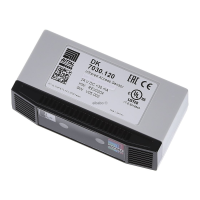
M4x25
M
A
= 1.5 ±
0.5Nm
ISO7380
Fig.22: Screw-fastening the designer compensating panel
including comfort handle (hinge on right)
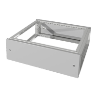
M4x25
M
A
= 1.5 ±
0.5Nm
ISO7380
Fig.23: Screw-fastening the designer compensating panel
including comfort handle (hinge on left)
5.5 Connecting the comfort handle
5.5.1 Connection to Access Control
The Access Control supplies the comfort handle with
the necessary operating voltage via the connection
cable. A separate power supply unit does not need to
be connected.
◾ First disconnect the CAN bus from the Access Con-
trol.
◾ Fit the handle to the door to be monitored (see sec-
tion5.4 "Installation procedure").
◾ Connect the handle via the connection cable to the
Access Control.
◾ Connect a reader unit to the Access Control with the
connection cable.
◾ Connect the CAN bus to the Access Control again.
5.5.2 Connection to external controller
Opening the comfort handle may alternatively be con-
trolled without an Access Control, connected coded
lock or transponder reader. In such cases, the required
voltage supply and the signal for opening the handle
lever must be provided by the external controller via the
PLC interface.
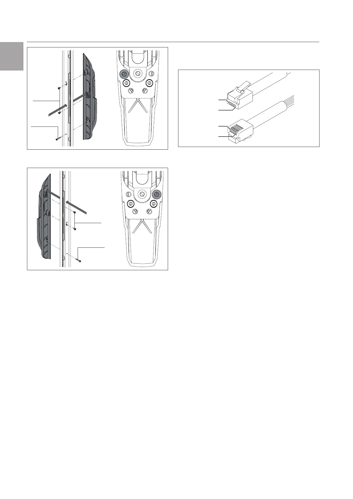
◾ For this purpose, please note the pin assignment of
the RJ12 connector on the comfort handle connec-
tion cable.
in 1
in 6
in 6
in 1
Fig.24: Connection pins on the RJ12 connector
Pin 1: +24V (supply voltage)
Pin 2: GND
Pin 3: RS485A
Pin 4: RS485B
Pin 5: Control signal for door latch (input)
Pin 6: Acknowledgement from handle lever (signal
output)
◾ Please also note the following:
– Pins 3 and 4 are not used for activation via the PLC
interface.
– The 24V DC control signal is needed to activate
and open the handle lever.
– The feedback signal "Gnd" on pin 6 means that
the handle lever is closed. The maximum current
capacity is 100mA.
 Loading...