EasyManua.ls Logo

RoboSense RS-Bpearl User Manual

RoboSense RS-Bpearl
56 pages
To Next Page IconTo Next Page
To Previous Page IconTo Previous Page
Page #38 background imageLoading...
Page #38 background image
33
RS-Bpearl User Manual
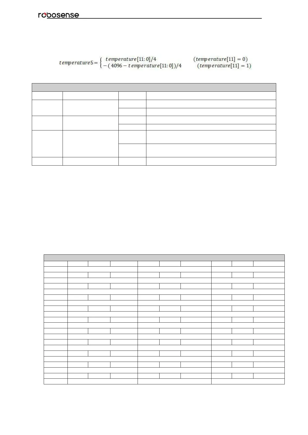
Temperature5 represents bottom board temperature. The temperature register contains 2
bytes to be temperature_reg[15:0]. temperature_reg[15:12] is invalid.
temperature_reg[11:0] is temperature value, while temperature_reg[15] is symbol flag.
(4) Byte16 represents the GPS input status register gps_st, this register uses 3 bits to
describe the validation for PPS, GPRMC, and timestamp. The details are shown below:
GPS input status register GPS_ST
BIT
Function
Value
Status
bit0
PPS_LOCK
0
PPS is invalid
1
PPS is valid
bit1
GPRMC flag:
GPRMC_LOCK
0
GPRMC is invalid
1
GPRMC is valid
bit2
UTC_LOCK
0
LiDAR internal timestamp is not synchronizing the
UTC.
1
LiDAR internal timestamp is synchronizing the
UTC.
bit3~bit7
Reserved
x
N/A
(1) The real-time rotation speed of the motor is composed of two bytes, byte32 and
byte33. The calculation formula is as follows:
Motor real-time rotation speed = (256 * r_rpm1 + r_rpm2)÷6
(2) The reset is used for internal debug, they are not opened.
B.12 ASCII code in GPRMC Packet
GPRMC register reserve 86 bytes, it can store the whole GPRMC message from GPS
module in to the register in ASCII code.
B.13 Corrected Vertical Angle (COR_VERT_ANG)
Corrected Vertical Angle96bytes in total
Byte No.
byte1
byte2
byte3
byte4
byte5
byte6
byte7
byte8
byte9
Function
Channel 1_COR_VERT_ANG
Channel 2_COR_VERT_ANG
Channel 3_COR_VERT_ANG
Byte No.
byte10
byte11
byte12
byte13
byte14
byte15
byte16
byte17
byte18
Function
Channel 4_COR_VERT_ANG
Channel 5_COR_VERT_ANG
Channel 6_COR_VERT_ANG
Byte No.
byte19
byte20
byte21
byte22
byte23
byte24
byte25
byte26
byte27
Function
Channel 7_COR_VERT_ANG
Channel 8_COR_VERT_ANG
Channel 9_COR_VERT_ANG
Byte No.
byte28
byte29
byte30
byte31
byte32
byte33
byte34
byte35
byte36
Function
Channel 10_COR_VERT_ANG
Channel 11_COR_VERT_ANG
Channel 12_COR_VERT_ANG
Byte No.
byte37
byte38
byte39
byte40
byte41
byte42
byte43
byte44
byte45
Function
Channel 13_COR_VERT_ANG
Channel 14_COR_VERT_ANG
Channel 15_COR_VERT_ANG
Byte No.
byte46
byte47
byte48
byte49
byte50
byte51
byte52
byte53
byte54
Function
Channel 16_COR_VERT_ANG
Channel 17_COR_VERT_ANG
Channel 18_COR_VERT_ANG
Byte No.
byte55
byte56
byte57
byte58
byte59
byte60
byte61
byte62
byte63
Function
Channel 19_COR_VERT_ANG
Channel 20_COR_VERT_ANG
Channel 21_COR_VERT_ANG
Byte No.
byte64
byte65
byte66
byte67
byte68
byte69
byte70
byte71
byte72
Function
Channel 22_COR_VERT_ANG
Channel 23_COR_VERT_ANG
Channel 24_COR_VERT_ANG
Byte No.
byte73
byte74
byte75
byte76
byte77
byte78
byte79
byte80
byte81
Function
Channel 25_COR_VERT_ANG
Channel 26_COR_VERT_ANG
Channel 27_COR_VERT_ANG
Byte No.
byte82
byte83
byte84
byte85
byte86
byte87
byte88
byte89
byte90
Function
Channel 28_COR_VERT_ANG
Channel 29_COR_VERT_ANG
Channel 30_COR_VERT_ANG
Byte No.
byte91
byte92
byte93
byte94
byte95
byte96
Function
Channel 31_COR_VERT_ANG
Channel 32_COR_VERT_ANG

Table of Contents

Questions and Answers:

RoboSense RS-Bpearl Specifications

General IconGeneral
ModelRS-Bpearl
Field of View360°
Laser Wavelength905 nm
TypeLiDAR
Weight0.92 kg
Accuracy±2 cm
Frame Rate10 Hz

Summary

Safety Notice

Introduction to RS-Bpearl

Product Specifications

Interface and Connectivity

Power Supply Details

Details power supply requirements and voltage for the RS-Bpearl.

LiDAR Data Output Interface

Describes the aviation terminal connector for LiDAR data output.

Interface Box Description

Explains the interface box for power, Ethernet, and GPS connections.

Interface Box Connection Diagram

Illustrates how to connect the interface box to power, GPS, and PC.

Communication Protocols

MSOP Protocol Details

Explains the Main Data Stream Output Protocol (MSOP), including its packet structure and data fields.

DIFOP Protocol Details

Details the Device Information Output Protocol (DIFOP) for monitoring device status and configuration.

UCWP Protocol Details

Introduces the User Configuration Write Protocol (UCWP) for device parameter reconfiguration.

GPS Synchronization

GPS Synchronization Theory

Explains how GPS synchronization works with PPS and GPRMC signals.

GPS Usage and Configuration

Details the GPS receiver connection and GPRMC message format.

Key Characteristics

Return Mode Options

Explains different return modes: Strongest, Last, and Dual.

Phase Lock Feature

Describes the phase-locking feature for synchronizing multiple sensors.

Point Cloud Mapping

Coordinate System Mapping

Explains the conversion from polar to XYZ Cartesian coordinates.

Troubleshooting Guide

Information Registers (Appendix B)

Motor Speed Settings

Explains the register for setting motor rotation speed and direction.

Ethernet Configuration Registers

Details registers for IP address, MAC address, and port numbers.

FOV Setting Parameters

Describes registers for setting the Field of View (FOV) range.

Motor Phase Offset Setting

Explains the register for adjusting motor phase offset.

Firmware and Version Information

Details formats for top/bottom board firmware and serial numbers.

UTC Time Register Details

Explains the register for setting and reading UTC time components.

Status Register Details

Describes registers for monitoring current, voltage, and power supply status.

Fault Diagnosis Registers

Details registers for temperature, error rates, and diagnostic status.

Corrected Vertical Angle Data

Defines the byte structure for corrected vertical angles per channel.

Corrected Horizontal Offset Angle Data

Defines the byte structure for corrected horizontal offset angles per channel.

RSView Software Usage (Appendix C)

RSView Software Features

Lists the capabilities of the RSView software for data visualization, recording, and analysis.

RSView Installation and Network Setup

Instructions for installing RSView, configuring network settings, and starting data visualization.

RSView Data Handling and Replay

Guides on saving streaming data to PCAP files and replaying recorded data.

RSView Firmware Parameter Settings

Instructions for setting factory firmware parameters like Rotate Speed and FOV.

RSView Data Port and Firmware Update

Guides on configuring RSView data ports and performing online firmware updates.

RSView Troubleshooting

Using the Fault Diagnosis tool within RSView to monitor and diagnose sensor parameters.

RS-Bpearl ROS Package Integration (Appendix D)

ROS Software Installation

Guide for installing Ubuntu and ROS Kinetic for the RS-Bpearl package.

Compiling the RS-Bpearl ROS Package

Steps to compile the ROS package for RS-Bpearl.

Configuring PC IP Address for ROS

Setting the PC's static IP address for communication within the ROS environment.

Displaying Real-time Data with ROS

Instructions to launch ROS nodes for visualizing real-time point cloud data.

Offline PCAP File Display with ROS

Steps to display recorded PCAP data using the RS-Bpearl ROS package.

LiDAR Cleaning and Maintenance (Appendix H)