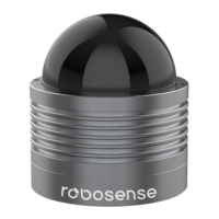
EasyManua.ls Logo

RoboSense RS-Bpearl User Manual

RoboSense RS-Bpearl
56 pages
To Next Page IconTo Next Page
To Previous Page IconTo Previous Page
Page #46 background imageLoading...
Page #46 background image
41
RS-Bpearl User Manual
Figure C 16: Set LiDAR information successful.
Note 1: during the process of parameter setting, please not cut off the power supply.
Otherwise, the internal parameters in LiDAR will be incorrectly saved.
Note 2: if the MSOP Port or the DIFOP Port is modified, please set the Data Port in
RSView first according to following section C.8 before reconnecting device.
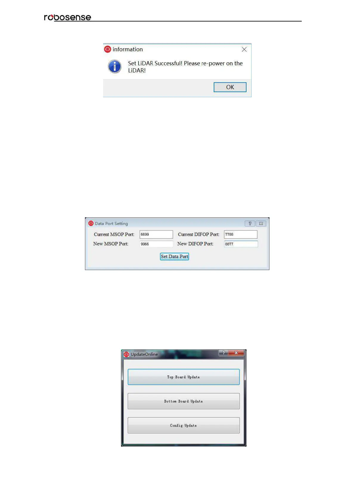
C.8 Setting RSView Data Port
The MSOP Port by default is 6699, and the DIFOP Port is 7788. If one of the two
parameters or both of them has been changed (just like the description in section C-7), the
new Data Port in RSView must be set and refreshed. Otherwise, the data won’t be
displayed. If the MSOP Port and DIFOP Port in RS-Bpearl are unknown or forgotten, user
can utilize the software Wireshark to capture the data packet from Dst Port.
Click Tools > Data Port, type the MSOP Port and the DIFOP Port changed, then click Set
Data Port.
Figure C-17: Set Data Port.
C.9 Firmware Update Online
Please ensure the connectivity of LiDAR, and point cloud can be displayed and get the
firmware information according to section C.8.
Click Tools > Online Update, as shown in Figure C-18, top board update and bottom board
update could be selected.
Figure C-18: Online Update.

Table of Contents

Questions and Answers:

RoboSense RS-Bpearl Specifications

General IconGeneral
ModelRS-Bpearl
Field of View360°
Laser Wavelength905 nm
TypeLiDAR
Weight0.92 kg
Accuracy±2 cm
Frame Rate10 Hz

Summary

Safety Notice

Introduction to RS-Bpearl

Product Specifications

Interface and Connectivity

Power Supply Details

Details power supply requirements and voltage for the RS-Bpearl.

LiDAR Data Output Interface

Describes the aviation terminal connector for LiDAR data output.

Interface Box Description

Explains the interface box for power, Ethernet, and GPS connections.

Interface Box Connection Diagram

Illustrates how to connect the interface box to power, GPS, and PC.

Communication Protocols

MSOP Protocol Details

Explains the Main Data Stream Output Protocol (MSOP), including its packet structure and data fields.

DIFOP Protocol Details

Details the Device Information Output Protocol (DIFOP) for monitoring device status and configuration.

UCWP Protocol Details

Introduces the User Configuration Write Protocol (UCWP) for device parameter reconfiguration.

GPS Synchronization

GPS Synchronization Theory

Explains how GPS synchronization works with PPS and GPRMC signals.

GPS Usage and Configuration

Details the GPS receiver connection and GPRMC message format.

Key Characteristics

Return Mode Options

Explains different return modes: Strongest, Last, and Dual.

Phase Lock Feature

Describes the phase-locking feature for synchronizing multiple sensors.

Point Cloud Mapping

Coordinate System Mapping

Explains the conversion from polar to XYZ Cartesian coordinates.

Troubleshooting Guide

Information Registers (Appendix B)

Motor Speed Settings

Explains the register for setting motor rotation speed and direction.

Ethernet Configuration Registers

Details registers for IP address, MAC address, and port numbers.

FOV Setting Parameters

Describes registers for setting the Field of View (FOV) range.

Motor Phase Offset Setting

Explains the register for adjusting motor phase offset.

Firmware and Version Information

Details formats for top/bottom board firmware and serial numbers.

UTC Time Register Details

Explains the register for setting and reading UTC time components.

Status Register Details

Describes registers for monitoring current, voltage, and power supply status.

Fault Diagnosis Registers

Details registers for temperature, error rates, and diagnostic status.

Corrected Vertical Angle Data

Defines the byte structure for corrected vertical angles per channel.

Corrected Horizontal Offset Angle Data

Defines the byte structure for corrected horizontal offset angles per channel.

RSView Software Usage (Appendix C)

RSView Software Features

Lists the capabilities of the RSView software for data visualization, recording, and analysis.

RSView Installation and Network Setup

Instructions for installing RSView, configuring network settings, and starting data visualization.

RSView Data Handling and Replay

Guides on saving streaming data to PCAP files and replaying recorded data.

RSView Firmware Parameter Settings

Instructions for setting factory firmware parameters like Rotate Speed and FOV.

RSView Data Port and Firmware Update

Guides on configuring RSView data ports and performing online firmware updates.

RSView Troubleshooting

Using the Fault Diagnosis tool within RSView to monitor and diagnose sensor parameters.

RS-Bpearl ROS Package Integration (Appendix D)

ROS Software Installation

Guide for installing Ubuntu and ROS Kinetic for the RS-Bpearl package.

Compiling the RS-Bpearl ROS Package

Steps to compile the ROS package for RS-Bpearl.

Configuring PC IP Address for ROS

Setting the PC's static IP address for communication within the ROS environment.

Displaying Real-time Data with ROS

Instructions to launch ROS nodes for visualizing real-time point cloud data.

Offline PCAP File Display with ROS

Steps to display recorded PCAP data using the RS-Bpearl ROS package.

LiDAR Cleaning and Maintenance (Appendix H)