26 Rockwell Automation Publication 440R-UM013F-EN-P - July 2021
Chapter 3 Power, Ground, and Wire
Example surge suppressors include the following catalog numbers:
• 100-FSD250 for Bulletin 100S contactors
• 1492-LD4DF terminal block with built-in 1N4007 diode
• 1492-JD3SS terminal block with built-in varistor
Single Wire Safety Input and
Output
The Single Wire Safety (SWS) feature allows a safety relay to expand the safety
function to additional safety relays using one wire, provided all safety relays
have the same voltage supply reference.
The CI and SI safety relays only have SWS outputs (terminal L11). The DI, DIS,
EM, and EMD safety relays have both SWS inputs (terminal L12) and SWS
outputs (terminal L11).
There can be many variations and combinations of series and parallel
connections of the SWS. Each L11 terminal can be connected to up to ten L12
terminals.
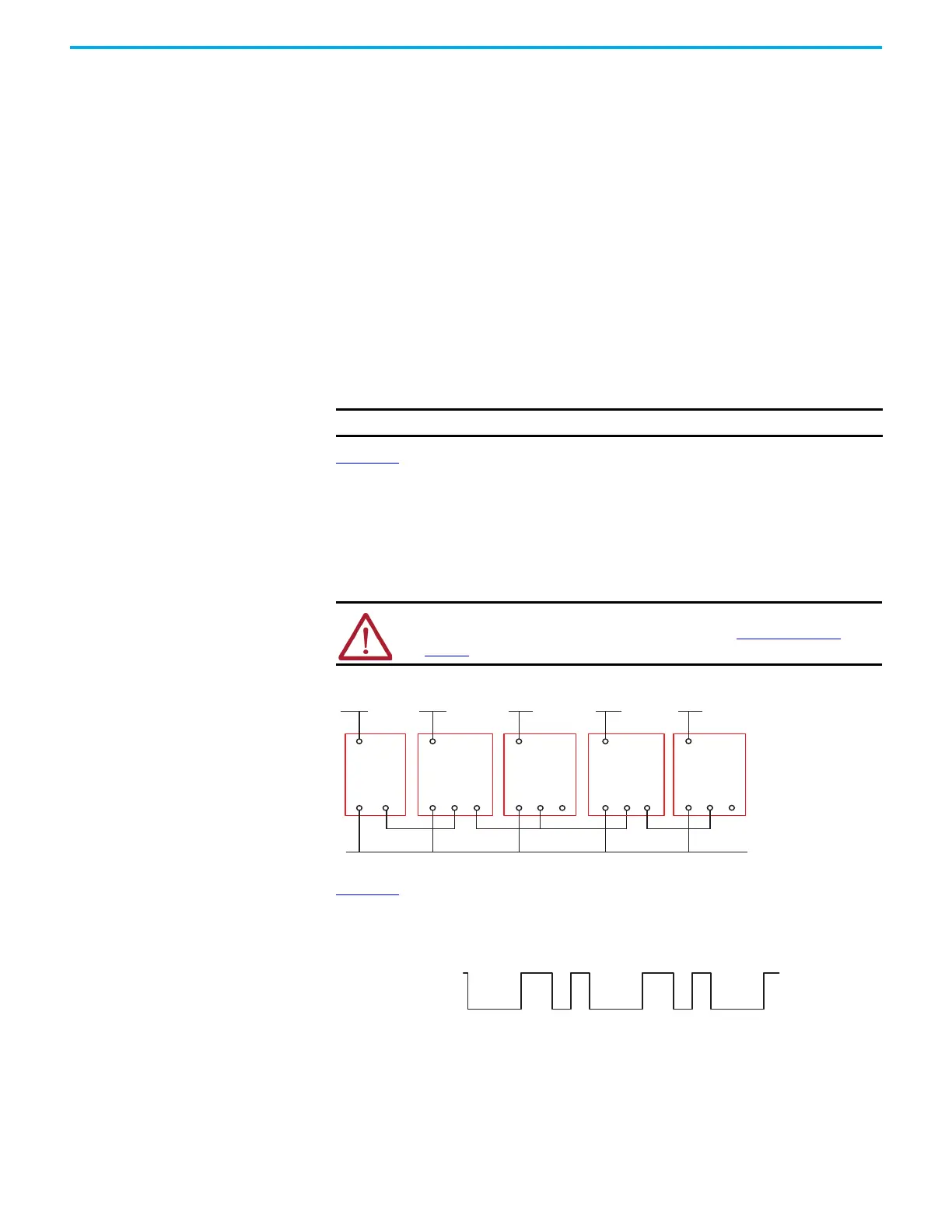
Figure 18
shows an example wiring diagram with SWS input from a DI safety
relay and SWS output connection to an EM safety relay in parallel with a DIS
safety relay. The safety relays must have a common power reference (24V
common). In this example, the safety function started by the CI or SI safety
relay is expanded to the DI safety relay. The safety functions monitored by the
DI safety relay are expanded to the EM and DIS safety relays. The safety
functions monitored by the DIS safety relay are expanded to the EMD safety
relay.
Figure 18 - Example SWS Connections
Figure 19 shows the characteristics of SWS signal when it is active. It starts
with a 1 ms pulse, followed 700 µs later by a 500 µs pulse. This waveform is
repeated every 4 ms. When inactive, the SWS is 0V.
Figure 19 - SWS Waveform
IMPORTANT Do not connect two or more L11 terminals together.
ATTENTION: You must consider the additional response time of each SWS
connection when calculating the safety distance. See Specifications on
page 77 for the response time for each relay.
L12 L11
A1
A2
+24V DC +24V DC
L11
A1
A2 L12 L11
A1
A2 L12 L11
A1
A2
+24V DC
SWS SWSSWS
+24V DC
L12 L11
A1
A2
+24V DC
24V DC Com (must have common reference)
CI or SI DI EM DIS EDM
 Loading...


