38 Rockwell Automation Publication 440R-UM013F-EN-P - July 2021
Chapter 6 Pulse Testing Functions
Figure 29 - Pulse Test Sequence for DI, DIS, and SI Safety Relays
Pulse Testing for OSSD
Outputs
The DIS safety relay has OSSD transistor outputs. One main transistor
supplies current to four individual transistors (see Figure 30). When the main
transistor is pulse tested, the pulse appears on all outputs. When the individual
transistors are tested, the pulse only appears on that transistor.
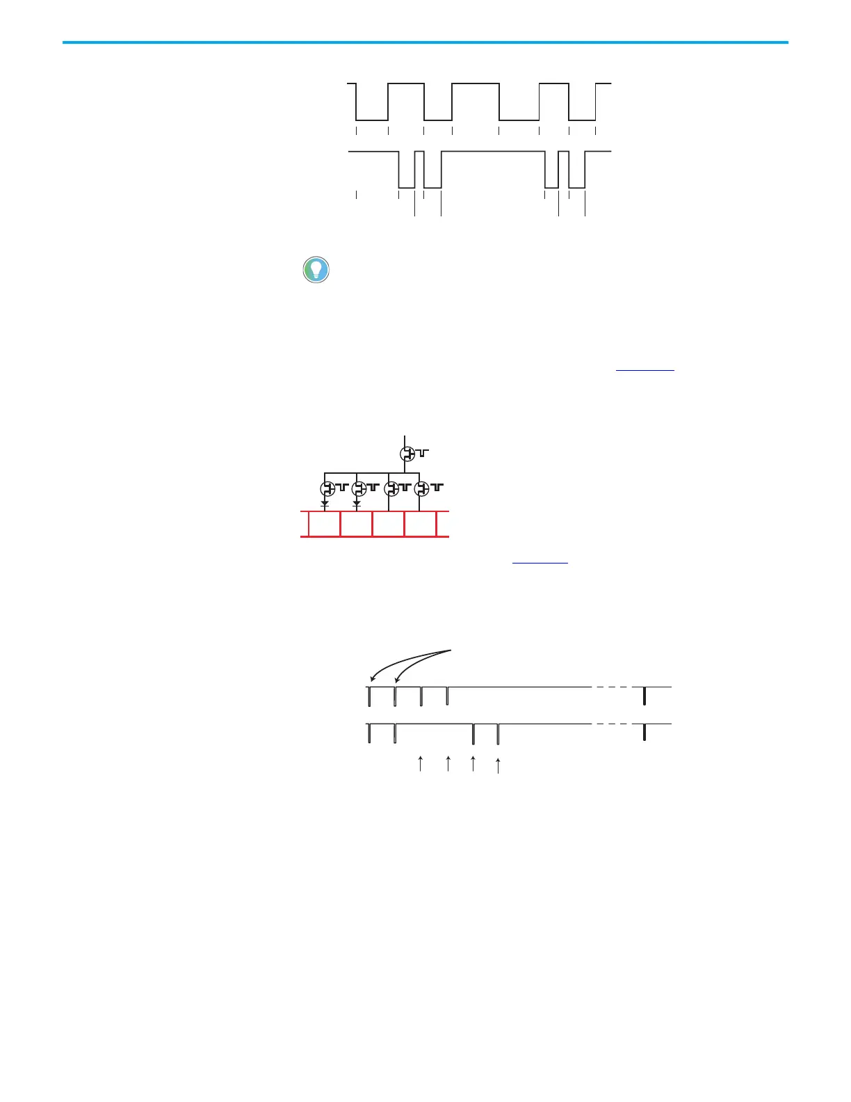
Figure 30 - Output Transistor Arrangement
The pulse test pattern is shown in Figure 31. The pulse widths vary from
50…150 µs. The pulse pattern on terminal 14 is identical to terminal 34, and the
pulse pattern on 24 is identical to 44. The pattern is repeated every
3.371seconds.
Figure 31 - OSSD Output Test Pulses on DIS Safety Relay
Although pulse tests appear on terminals 34 and 44, the DIS safety relay does
not detect faults from A1 to 34, 44 or between 34 and 44 when the outputs are
ON.
When using a digital voltmeter, S11 measures approximately 14V DC and S21
measures approximately 18V DC when the supply voltage to A1 is 24VDC and the
input circuits are open.
0
24V
0V
S11
S21
24V
0V
4 6.4
5.5 8
17.7 20
19
03
6.4
9 13.6 16.8 20 22.5
21.5
Main Transistor
Individual Transistors
24V
0V
24V
0V
0 131 524 655 3371 (ms)
262 393
Main Transistor Test
Terminals
14 and 34
24 and 44
Individual Transistor Tests Repeats
 Loading...


