Rockwell Automation Publication 440R-UM013F-EN-P - July 2021 37
Chapter 6
Pulse Testing Functions
Safety relays use pulse testing of inputs and outputs to verify that the safety
function is performed when called upon. Pulse testing for the inputs must be
used with devices with mechanical contacts like E-stop push buttons, tongue
operated interlock switches, and limit switches. The pulse testing cannot be
turned on or off and cannot be changed.
The test pulses are used to detect three short circuit conditions:
• Between the input terminals and +24V.
• Between the input terminals and 24V common.
• Between the two input terminals.
Pulse Testing for Inputs Pulse testing for the inputs is generated on terminals S11 and S21 of the CI, DI,
DIS, and SI safety relays. The EM and EMD safety relays do not use pulse
testing.
CI Safety Relay
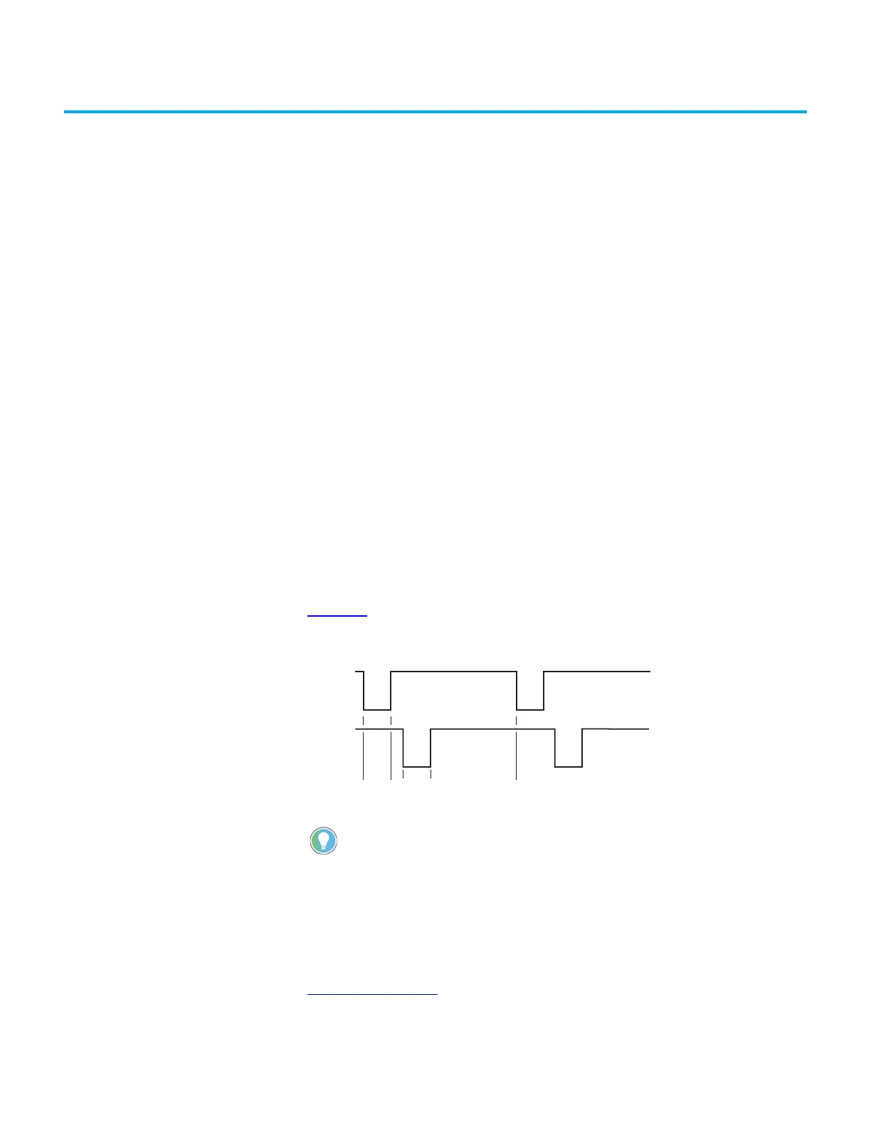
The pulse testing that is associated with the CI safety relay is shown in
Figure 28. The pulse widths are 2.5 ms wide. The pulse testing on S11 and S21 is
offset by 1 ms. The pulses are repeated every 14 ms.
Figure 28 - Pulse Test Sequence for CI Safety Relay
DI, DIS, and SI Safety Relays
The pulse test sequence for the DI, DIS, and SI safety relays are shown in
Figure 29 on page 38. The sequence is repeated every 13.6 ms.
When using a digital multimeter, S11 measures approximately 19V and S21
measures approximately 19V when the supply voltage to A1 is 24V DC and the input
circuits are open.
At the minimum-rated input ON voltage (11V), a DC multimeter reads approximately
8.9V DC at S12 and S22.
0
24V
0V
S11
S21
24V
0V
2.5 3.5 6 14
 Loading...


