72 Rockwell Automation Publication 440R-UM013F-EN-P - July 2021
Chapter 11 Troubleshooting
Auxiliary Output Issues
Measure the Auxiliary Output Terminal Voltage
When OUT status indicator is OFF, my PLC does not know that the relay is OFF
or my auxiliary status indicator does not turn ON.
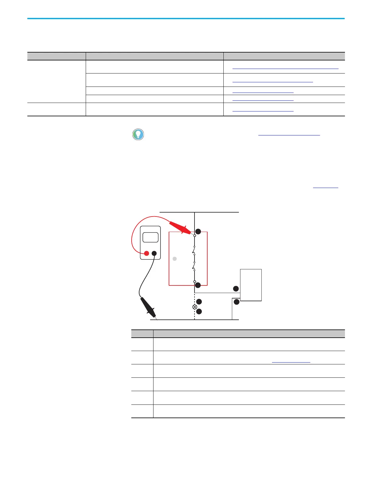
Confirm that voltage is present at the relay terminals and the load. Figure 83
shows an example of the measurement points for one output channel (41/42).
Figure 83 - Measure Voltage Aux Output Terminals
Measure the Contact Resistance
The OUT status indicator is OFF, and the voltage at terminal 41 is the same as
the supply voltage. However, terminal 42 measures 0V.
Table 18 - Auxiliary Output Issues
State Symptom Action
The OUT status indicator is
OFF.
My PLC does not know that the relay is OFF or my auxiliary status
indicator does not turn ON.
See Measure the Auxiliary Output Terminal Voltage
on page 72.
The voltage at terminal 41 is the same as the supply voltage. However,
terminal 42 measures 0V.
See Measure the Contact Resistance on page 72.
Terminal Y32 does not turn ON. See Check the Y32 Output
on page 73.
Terminal X32 does not turn ON. See Check the X32 Output
on page 74.
The safety outputs are OFF.
The Y32 output must be ON. This is true for both faulted and running
states.
See Check the Y32 Output
on page 73.
For more information on auxiliary outputs, see Auxiliary Output on page 27.
Step Description
1
The voltage at 41 must be the same as the supply voltage. If not, check for an open circuit (broken
wire), blown fuse, or tripped circuit breaker.
2
The voltage at 42 must be the same as the supply voltage. If not, the positive-guided relay inside GSR
safety relay is not closing. Measure the contact resistance; see Figure 84 on page 73
.
3
The voltage at the PLC input must be the same as the supply voltage. If not, check for an open circuit
(broken wire), a bad contact at a terminal connection), or go to step 4.
4
Place the black test probe on the PLC common terminal. Verify that the common of the PLC is
connected to the common of the voltage supply.
5
The aux output voltage at one side of the auxiliary status indicator must be the same as the supply
voltage. If not, check for an open circuit (broken wire) between terminal 14 and aux status indicator.
6
Verify that the aux status indicator is connected to the voltage supply common. The aux status
indicator must be replaced.
42
+Vs
41
Volts
DMM
1
2
3
4
5
Com
OUT
6
 Loading...


