Rockwell Automation Publication 440R-UM013F-EN-P - July 2021 33
Chapter 4 Configuration
Example 1: The range setting is 3 (starting with the Time set to 1), and the Time
setting is 5. Then the off-delay is: 30 s * 50% = 15 seconds
Example 2: The range setting is 6 (starting with the Time set to 10), and the
Time setting is 1. Then the on-delay is: 3000 s * 10% = 300 seconds
Configuration Process Configuration is a five-step process. The process requires the wiring to be
completed and the inputs closed. During the configuration process, GSR safety
relays send out test pulses to determine how it is wired and then configures the
internal parameters to match the application.
Five Steps to Configure Your GSR safety relay
1. With the power OFF, prepare the switches.
2. Apply power.
After a short wait, the PWR/Fault status indicator flashes red
continuously at a 1 Hz rate (0.5 s ON, 0.5 s OFF). The prior
configuration in the EEPROM is erased, and the device is now
prepared for a new configuration.
3. Adjust the Logic, Reset, Time, and Range switch settings as needed for
your application.
4. Verify the settings by counting the blink rates of the status indicators.
Table 8 on page 34
shows the indicator that flashes for the
corresponding switch setting for each relay.
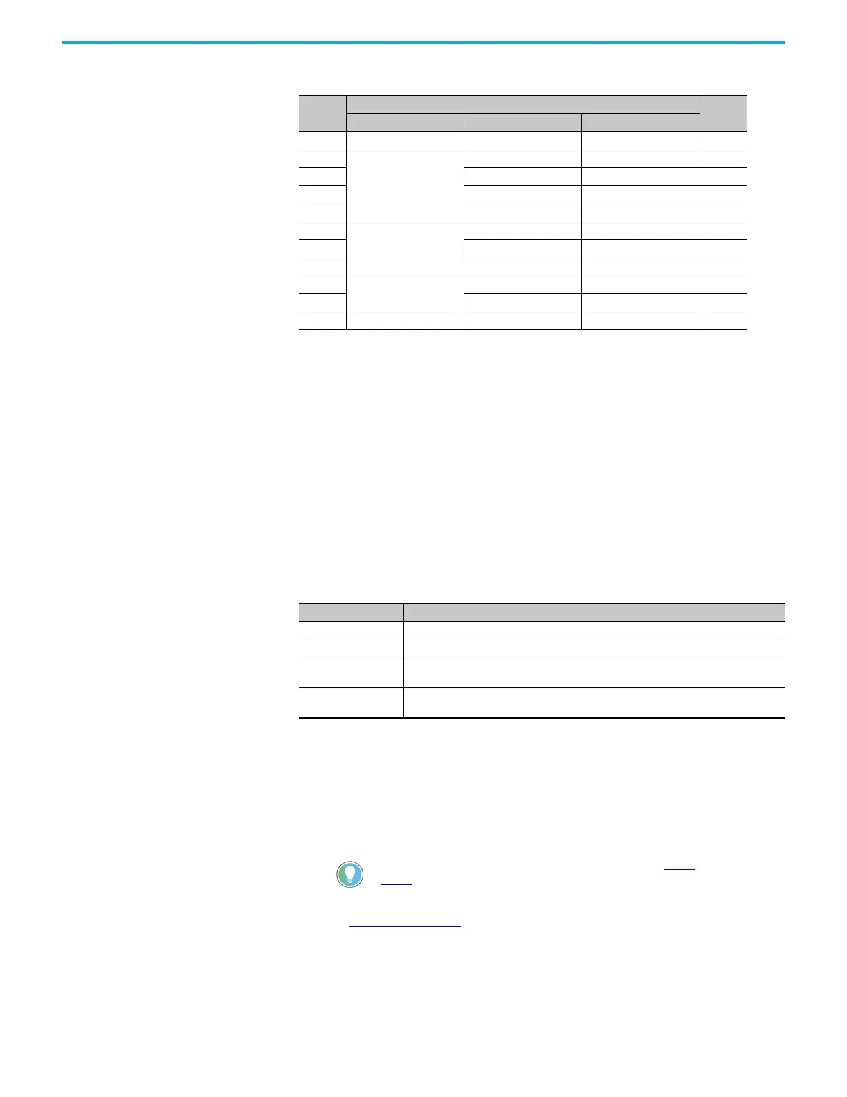
Table 7 - EMD Safety Relay Range and Time Settings
Position
Range
Time
Function Range (Time 1) [s] Range (Time 10) [s]
0Start Configuration — — —
1
Off Delay
0.1…1 10…100 10
2 1…10 100…1000 20
3 3…30 300…3000 30
430…300—40
5
On Delay
0.3…3 30…300 50
6 3…30 300…3000 60
730…300—70
8
Jogging
0.1…10 100…1000 80
9 3…30 300…3000 90
10———100
Safety Relay Action
DI/DIS Set the Logic switch to position 0.
CI/SI Set the Reset switch to position 0
EMD expansion safety
relay
Set the Range switch to position 0 and set Time switch to 1 (short timing range) or 10 (long
timing range).
EM expansion safety
relay
No switches. No action necessary.
You can change (or readjust) the switch settings during step 3 and
step 4. The power status indicator momentarily flashes red again.
 Loading...


