10 Rockwell Automation Publication 440R-UM010C-EN-P - September 2016
Chapter 2 Installation
Removal - To remove the GLT safety relay, use a screwdriver to pry the DIN
rail latch downwards until it is in the unlatched position. Then, swing the
module up.
Spacing - The GLT safety relay can be mounted directly next to other GSR
safety relays. When the GSR Ethernet Module is used, the GSR must be
mounted with 10mm (0.4 in.) of its neighboring module to maintain effective
communication.
Maintain 50.8mm (2in.) of space above and below the relay for adequate
ventilation.
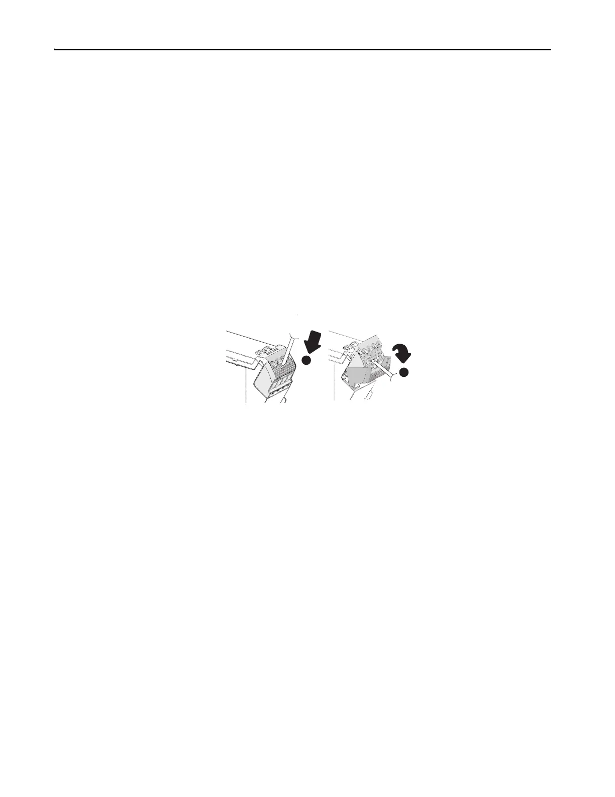
Removable Terminals
The GLT safety relay has removable terminals to ease wiring and replacement.
Figure 5 - Removable Terminals
1. Insert the tip of a small screwdriver into the slot near the terminal
screws.
2. Rotate the screwdriver to unlock the terminal block.
The terminal block can then be removed from the housing.
Enclosure Considerations
Most applications require installation in an industrial enclosure to reduce the
effects of electrical interference and environmental exposure. Pollution
Degree 2 is an environment where normally only non-conductive pollution
occurs except that condensation occasionally causes temporary conductivity.
Overvoltage Category II is the load level section of the electrical distribution
system. At this level, transient voltages are controlled and do not exceed the
impulse voltage capability of the products insulation.
This equipment is intended for use in a Pollution Degree 2 industrial
environment, in overvoltage Category II applications (as defined in IEC
60664-1), at altitudes up to 2000 m (6562 ft) without derating. This
equipment is considered Group 1, Class A industrial equipment according to
IEC/CISPR 11. Without appropriate precautions, there may be difficulties
with electromagnetic compatibility in residential and other environments due
to conducted and radiated disturbances.

 Loading...


