Rockwell Automation Publication 440R-UM010C-EN-P - September 2016 21
Power, Ground, and Wire Chapter 3
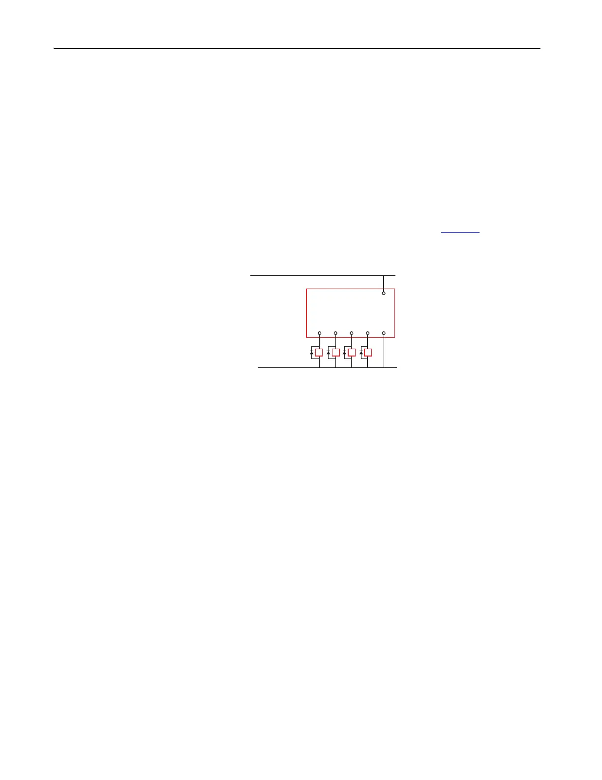
Use Surge Suppressors
Because of the potentially high current surges that occur when switching
inductive load devices, such as motor starters and solenoids, the use of some
type of surge suppression to help protect and extend the operating life of the
controllers output is required. By adding a suppression device directly across
the coil of an inductive device, you prolong the life of the outputs. You also
reduce the effects of voltage transients and electrical noise from radiating into
adjacent systems.
The following diagram shows an output with a suppression device. We
recommend that you locate the suppression device as close as possible to the
load device. Since the outputs are 24V DC, we recommend 1N4001 (50V
reverse voltage) to 1N4007(1000V reverse voltage) diodes for surge
suppression for the OSSD safety outputs, as shown in Figure 19
. The diode
must be connected as close as possible to the load coil.
Figure 19 - Surge Suppression
Example suppressors include:
• Catalog number 100-FSD250 for legacy Bulletin 100S Contactors
• Catalog number 100S-C**EJ contactors have built in suppression
• Catalog number 1492-LD4DF terminal block with built-in 1N4007
diode
• Catalog number 700-ADL1R is diode for catalog number 700-
HPSXZ24 positive-guided relay
Single Wire Safety (SWS)
The GLT safety relay has two single wire safety connections:
• Terminal L12 (input)
• Terminal L11 (output)
These terminals can only be connected to other devices that support single
wire safety. When the SWS input is ON, the Logic IN indicator turns ON.
GLT
L61512414
A1
A2
+24V DC
24V DC Com
K2 K3 K4K1

 Loading...


