Rockwell Automation Publication 440R-UM010C-EN-P - September 2016 25
Chapter 4
Configuration
Logic Switch Setting
The Logic switch determines the operating function of the GLT safety relay
and is used to set the configuration. If only the Range or Time setting must be
changed, the configuration process must start by setting the Logic switch to 0
or 9 when power is off.
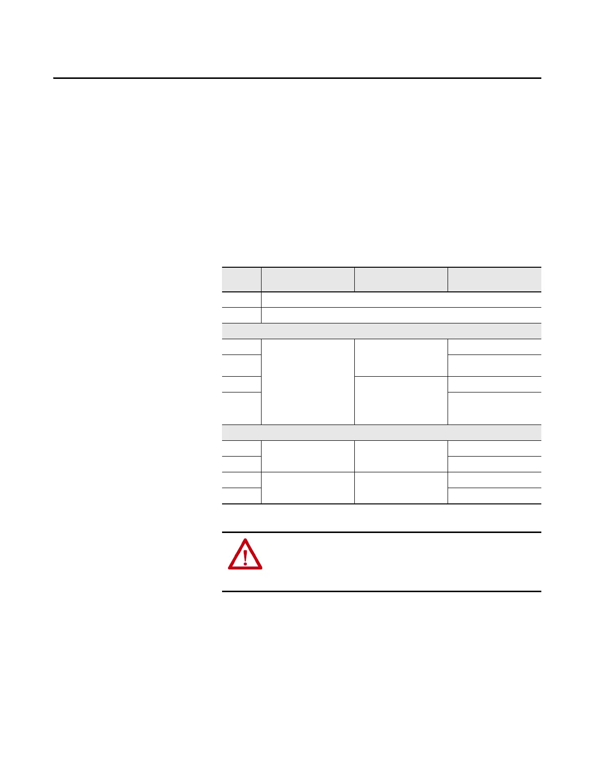
Table 2 - Logic Switch Setting
Switch 1
Setting
Lock/ Unlock Demand
Configuration
Delay Configuration Safety Inputs
0 Program mode (Pulse testing is activated on terminals 14, 24, 51, and L61
9 Program mode (Pulse testing is deactivated on terminals 14, 24, 51, and L61
Function 1 - Guard Locking Applications
1 Manual monitored Cat. 0 Stop.
14, 24, L11, Y32 immediate OFF
51, L61 delayed ON
Logic IN OR IN1
2 Logic IN AND IN1
3Cat. 1 Stop
14, 24, L11 delayed OFF
51, L61 delayed ON
Y32 immediate OFF
Logic IN OR IN1
4 Logic IN AND IN1
Function 2 - E-stop Applications
5 Manual monitored 14, 24, L11, Y32 immediate OFF
51, L61 delayed OFF
Logic IN OFF OR IN1
6 Logic IN AND IN1
7 Auto reset 14, 24, L11, Y32 immediate OFF
51, L61 delayed OFF
Logic IN OFF OR IN1
8 Logic IN AND IN1
ATTENTION: When the GLT safety relay is configured for settings 5 or 7 and
an E-stop device is connected to IN1, there must be no connection to the
Logic IN (terminal L12). E-stops must always be available and cannot be
bypassed or muted with 'OR' logic.

 Loading...


