
 Loading...
Do you have a question about the Rockwell Automation Allen-Bradley 440R-GL2S2T and is the answer not in the manual?
| Series | 440R |
|---|---|
| Type | Safety Light Curtain |
| Number of Contacts | 2 |
| Input Voltage | 24V DC |
| Operating Voltage | 24V DC |
| Mounting Type | DIN Rail |
| Number of Beams | 2 |
| Protected Height | 300 mm |
| Safety Integrity Level | SIL 3 |
| Performance Level | PLe |
| Safety Category | Category 4 |
| Category | Safety Relays |
| Standards | IEC 61496-1, EN 61496-1, IEC 61508, EN 61508, ISO 13849-1, EN ISO 13849-1 |
| Operating Temperature | -10°C to +55°C |
| Contact Configuration | 2 N/O |
| Response Time | 20 ms |
Details recent updates and additions in the manual for the GLT safety relay.
Identifies the target audience for the GLT safety relay user manual.
Explains the manual's role as a reference for GLT relay installation and troubleshooting.
Lists related documents and online resources for Rockwell Automation products.
Provides definitions for key terms and abbreviations used in the GLT safety relay manual.
Describes the physical components and characteristics of the GLT safety relay.
Explains the two primary safety functions the GLT relay can perform.
Details the application of the GLT relay for guard locking scenarios.
Describes the use of the GLT relay for emergency stop (E-stop) applications.
Provides physical dimensions and mounting specifications for the GLT safety relay.
Explains the procedure for attaching and removing the relay from a DIN rail.
Details the feature of removable terminals for easier wiring and replacement.
Discusses requirements for mounting the relay within an appropriate enclosure.
Offers guidance on managing heat dissipation for optimal relay performance.
Outlines essential guidelines and best practices for wiring the GLT safety relay.
Specifies the appropriate wire gauge for connections to the relay terminals.
States the recommended torque value for terminal screws.
Lists and describes the function of each terminal on the GLT safety relay.
Explains the grounding requirements for the GLT safety relay.
Details how to connect a compatible 24V DC power supply to the relay.
Discusses the connection of various safety devices to the GLT relay.
Explains wiring for safety devices using mechanical contacts.
Details connecting safety devices with OSSD outputs.
Describes how to wire the input for requesting gate unlock.
Explains wiring for the input that requests locking and resetting.
Covers the functionality and wiring of the retriggerable input.
Details the configuration and connection of the relay's outputs.
Advises on using surge suppressors for inductive loads.
Introduces the Single Wire Safety (SWS) feature.
Explains how the SWS input functions based on logic switch settings.
Describes variations and combinations for connecting SWS terminals.
Explains how the logic switch determines the relay's operating function.
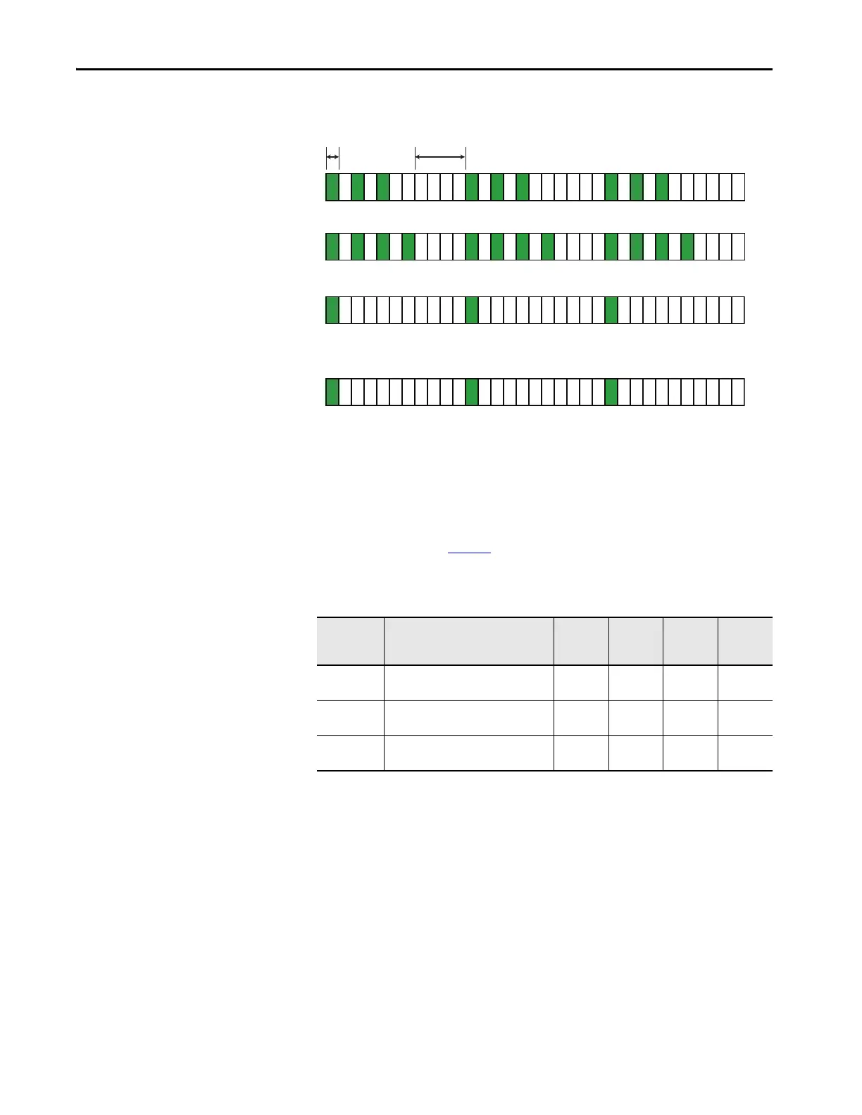
Details how the range switch sets the maximum delay time.
Describes how the time switch adjusts the delay time.
Guides on using the multi-position rotary switches for configuration.
Outlines the step-by-step procedure for configuring the GLT safety relay.
Lists the five distinct steps required for successful configuration.
Provides specific information and checks for each step of the configuration process.
Explains the behavior of status indicators during the relay's self-check.
Describes the meaning of status indicator lights during normal use.
Details how flashing indicator patterns signal specific faults and diagnostic information.
Covers further diagnostic information provided by the IN1 status indicator flash rates.
Explains the active pulse testing of input terminals S11 and S21.
Describes the pulse testing performed on output terminals 14, 24, 51, and L61.
Provides general technical specifications like dimensions, weight, and wiring.
Details environmental operating conditions such as temperature and humidity.
Lists detailed electrical specifications for the IN1 input signals.
Specifies parameters for the lock and unlock request inputs.
Provides specifications for the retrigger input.
Details the specifications for the relay's output terminals.
Specifies continuous and surge output current for lock/unlock signals.
Lists specifications for the auxiliary Y32 output signal.
Details electrical specifications for the SWS input signal.
Lists specifications for the SWS output signal.
Shows recovery times for various logic settings and inputs.
Provides response times for different inputs and logic settings.
Lists the various certifications the GLT safety relay has obtained.
Details CE marking and compliance with EU directives for the product.
Explains the product's compliance with the European Machine Safety Directive.
Provides Safety Integrity Level (SIL) data according to IEC standards.
Details the Performance Level (PL) and Category ratings per ISO 13849-1.
Outlines compliance with the Electromagnetic Compatibility (EMC) Directive.


