34 Rockwell Automation Publication 440R-UM010C-EN-P - September 2016
Chapter 6 Pulse Testing Functions
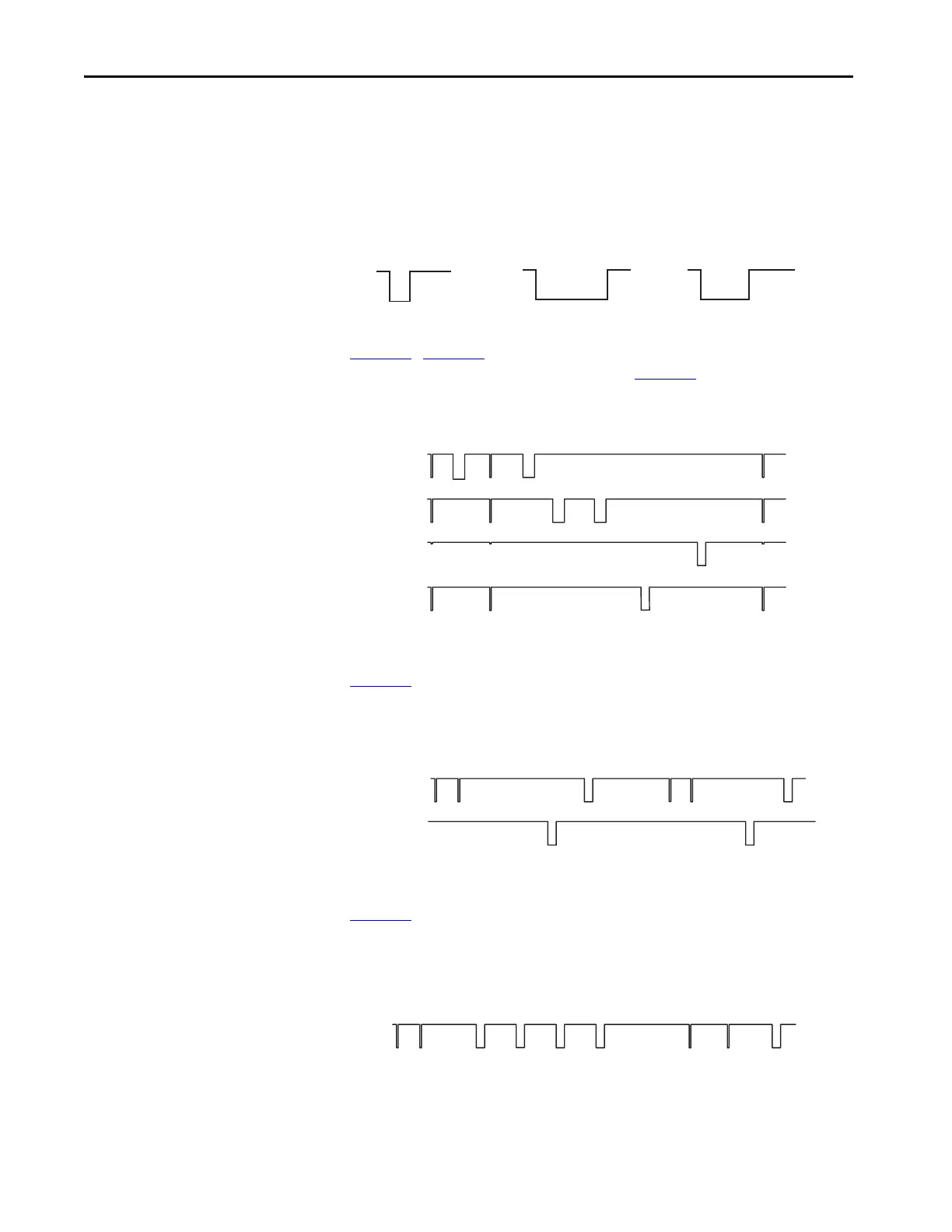
When pulse testing is configured (start with Logic Setting 0), the main
transistor tests the outputs, which are then tested individually. The main
transistor test pulse is 50 µs wide. The pulse width on terminals 14 and 24 is
350 µs wide, and the pulse width on terminals 51 and L61 is 200 µs wide.
Figure 26 - Output Pulse Test Width
Figure 27…Figure 29 show the pulse test pattern. This pattern depends on the
GLT safety relay configuration and its state. Figure 27
shows the pulse pattern
for E-stop configurations. The pattern is repeated every 3750 ms.
Figure 27 - Output Pulse Test Pattern for E-stop Functions
Figure 28 shows the pulse test pattern on 51 and L61 when the GLT safety
relay is configured as two high side outputs. The pattern is repeated every
2639 ms.
Figure 28 - Output Pulse Test Pattern for Two High Side Guard Locking
Figure 29 shows the pulse test pattern on 51 and L61 when the GLT safety
relay is configured as a high side/low side outputs. Terminal 51 is referenced to
L61, not 24V common. The pattern is repeated every 2639 ms.
Figure 29 - Output Pulse Test Pattern for High/Low Side Guard Locking
24V
00
0V
50 µs 350 µs
24V
0V
Main Transistor 14 & 24
0
200 µs
24V
0V
51 & L61
24
14
Terminal
24V
0V
24V
0V
24V
0V
24V
0V
L61
51
145
Approximate Time (ms)
220 290 439 585 2345 2487 37500
erminal
24V
0V
24V
0V
L61
51
Approximate Time (ms)
154 1649 1753 2639 2793 4287 43910
erminal
L61
51
Approximate Time (ms)
154 925 1132 1339 1545 2639 2793 35640