42 Rockwell Automation Publication CC-QS034C-EN-P - March 2015
Chapter 2 System Validation
Validate Your System
In this section, you review the Machine Functions screen and explore the Status and Command screens to test the manual
control of the building block.
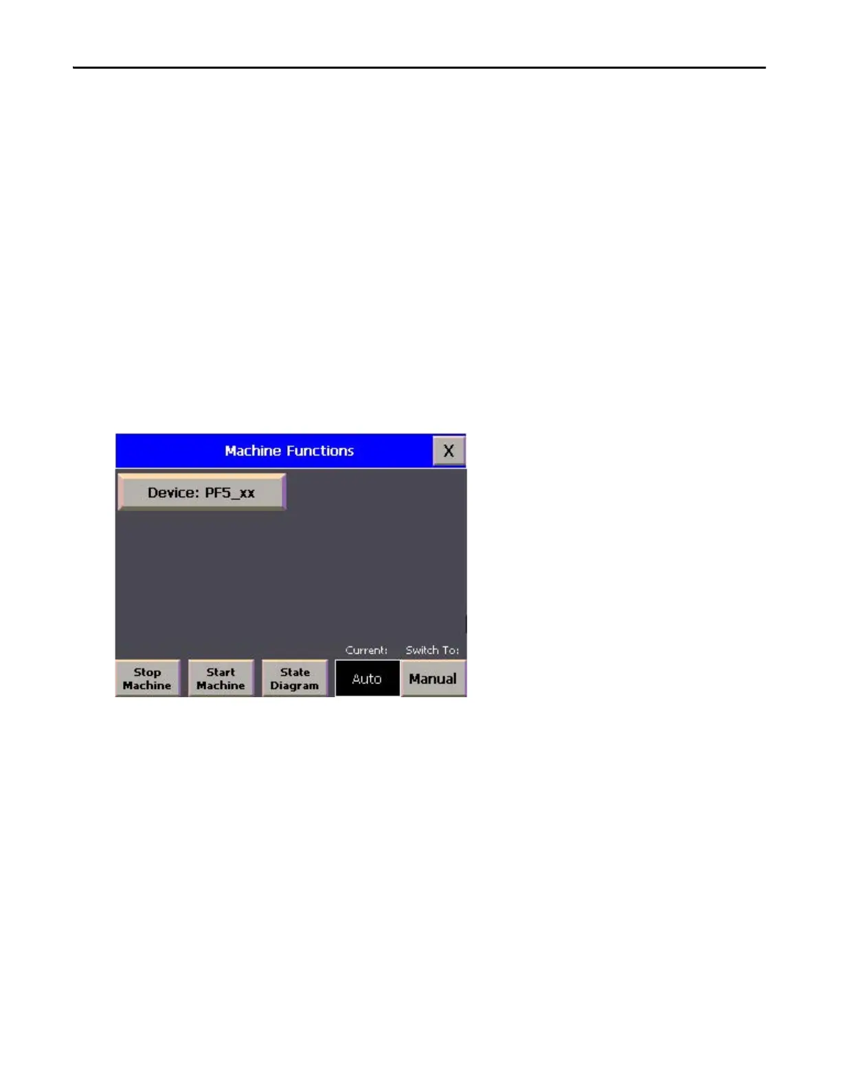
Understand the Machine Functions Screen
The Machine Functions screen is the screen that links to the installed building blocks. When this screen is first loaded, you
can complete the following tasks:
• Return to the Machine Overview screen by pressing the ‘X’ in the upper right-hand corner of the screen.
• View a device in detail by pressing its button.
• View the current machine Auto/Manual state.
• Change the current machine Auto/Manual state.
• Clear machine faults, start/stop the machine (while in Auto mode) and go to the machine state diagram overview
screen.
The border of the device button changes color to indicate a specific status. For PowerFlex AC drives, the button border
colors indicate the following status:
• A green border indicates that the drive is active and running.
• A gray border indicates that the drive is inactive and stopped.
• A red border indicates that there is a fault or an alarm is present.

 Loading...