ep-70/90 Feb. 2000
11
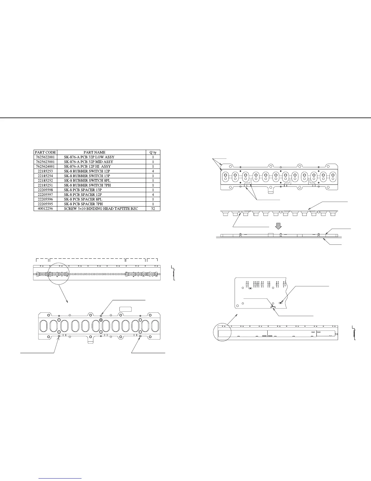
2)次に、SPACER の丸穴部に RUBBER SWITCH のボスを位置決め
して、SPACER と同様に低音側より順に RUBBER SWITCH 13P,
RUBBER SWITCH 7PH と置いていきます。
この際、RUBBER SWITCH と SSPACER の外形切 (fig.3 fig.4
参照のこと)
3)次に、PCBの切り欠き部とSPACERの凸部を目印として、SPACER
の位置決めピンに PCB の位置決め穴がはまるように PCB をおき
ます。(fig.5 参照のこと)
PCB は、fig.6 で示されるように LOW, MID, HI の 3 枚で構成され
ています。
2) Then, locate the bosses of the RUBBER SWITCHes in the round
holes of the SPACERs, and as done for the SPACERs, put one
RUBBER SWITCH 8PL, four RUBBER SWITCH 12P, one RUB-
BER SWITCH 13P, one RUBBER SWITCH 7PH in order, start-
ing on the lower tone side.
At this time, carefully match the positions of the RUBBER
SWITCHes, SPACER notches and air grooves. ( See Fig.3 and
Fig.4 )
3) Then, put the PCBs so that the positioning pins of the SPACERs
fit into the positioning holes of the PCBs.
At this time, use the PCB notch and spacer lug as a guide.
( See Fig.5 )
As shown in Fig.6, there are three PCBs, LOW, MID and HI.
分解手順
1. 基板の取り付け方
1)まず、シャーシを左右が逆にならないように裏返します。
次に、fig.1 に示すように左側(鍵の低音側)より、先ず SPACER
8PL を 1 個、そして SPACER 12P を4個、シャーシの位置決め穴
に合わせて順に置いていきます。(fig.2 参照のこと)
右側(高音側)にはSPACER 13P、SPACER 7PHを同様に置きます。
DISASSEMBLY
1.INSTALLATION OF PCB'S
Reauired Parts
1) First,turn the chassis over, noting that the right-and-left-hand
sides are not revered.
Then, as shown in Fig.1, put one SPACER 8PL and four SPAC-
ERs 12P in this odrer, starting on the left-hand side
( lower tone side of the keyboard ) according to the chassis posi-
tioning holes. ( See Fig.2. )
Similarly, put the SPACER 13P and SPACER 7PH on the right-
hand side ( higher tone side ) .
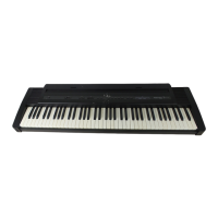
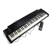
KEYBOARD SK-8P76-B (ep-70)
/鍵盤 SK-8P76-B (ep-70)
Treble SideBass Side
SPACER 7PHSPACER 8PL
Positioning Hole of chassis
SPACER 13PSPACER 12P ×4
Positioning Hole of chassis
Positioning Hole of Chassis
fig. 2
fig. 1
Cutout Part
Air-Escape Groove
fig. 4
Chassis
PCB SPACER
RUBBER SWITCH
Positioning Boss (6 points)
fig. 3
12P HI
32 P MID
Treble SideBass Side
Positioning Pin of SPACER
PCB Cutout Part
Projecting Part of SPACER
fig. 5
32P LOW
fig. 6
/必要部品
 Loading...