20
Jan.2003
recovery is performed.
Set this “Off” if you want to perform the recovery while leaving the
project(s) of the recover-destination drive as they are.
• CD Speed
Selects the speed at which the CD-R/RW disc will be read.
4. Select the recover-destination.
Press the [F4 (SelDrv)] button to access the Drive Select screen.
To exit Drive Select, press the [F6 (CANCEL)] button.
5. Press the [F5 (OK)] button.
The “STORE Current?” (Store the current project?) dialog box will
appear. Press the [EXIT/NO] button.
6. If the backup spanned more than one disc, the disc will be ejected and a
message of “Insert Disk #” (# is the disc number) will appear.
Insert the disc of the appropriate number and press the [ENTER/YES]
button.
When project recover is completed, you will return to Project Condition.
TEST MODE
Required equipment
• VS8F-2 (three pcs.)
• R-BUS device (recommended: ADA-7000)
• Foot switch
• Audio device (with digital output)
• A device that can output a SMPTE signal
• Cables (audio)
• Tester (a device that can measure voltages)
Starting test mode
To enter Test mode, hold down the [PAGE] and [F1] buttons located below the
LCD, turn on the power of the VS-2400CD.
Exiting test mode
Turn off the power of the VS-2400CD.
Basic operation
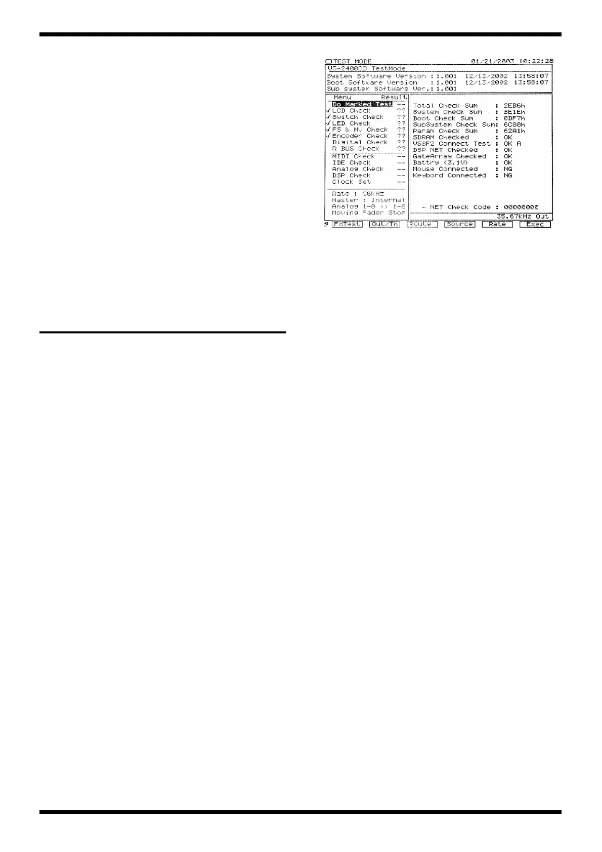
When the test program is started up as described above, the LCD screen of
“Fig.1” will appear.
The upper part of the LCD screen always shows the current version number.
The lower left of the LCD screen shows the test menu and the current audio
input/output checking mode.
The lower right of the screen shows the contents of the selected menu.
Use the [TIME/VALUE] knob to select a test item, and use the [F6] button to
execute it.
Explanation of items checked
when Test mode starts
Here we explain the checked items shown in the lower right of the screen
when Test mode is started.
fig.1
[SDRAM Checked]
Indicates the result of checking SDRAM.
If there is a problem with this, Test mode will not start up.
[VS8F2 Connect Test]
Checks the VS8F-2 connection.
1. The name of the connector on which the VS8F-2 is installed will be
displayed.
2. If all are installed, “A” and “B” will be displayed.
3. If the result is satisfactory, the display will indicate “OK.” If there is a
problem, or if none are installed, the display will indicate “NG.”
[DSP NET Checked]
Main board IC53, IC54, IC55, IC56, IC57, IC58, and VS8F-2 will be checked.
If satisfactory, the display will indicate “OK.” If a problem is found, the
display will indicate “NG.”
[GateArray Checked]
Main board IC38 and IC46 will be checked.
If satisfactory, the display will indicate “OK.” If a problem is found, the
display will indicate “NG.”
[Battery]
The lithium battery on the main board will be checked.
1. If satisfactory, the display will indicate “OK” and show the voltage of the
battery.
2. If unsatisfactory, the display will indicate “NG” and show the voltage of
the battery.
3. If no battery is installed, the display will indicate “<No Battery>”.
[Mouse Connected]
The mouse connection will be checked.
1. If a mouse is connected and is operating normally, the display will
indicate “OK.”
2. If a mouse is not connected, or if there is a problem, the display will
indicate “NG.”
 Loading...