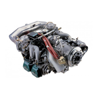
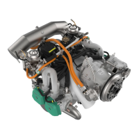
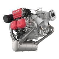
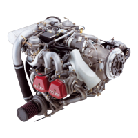
7.1) Cooling system
System Overview
The cooling system of the engine is designed for liquid cooling
of the cylinder heads and ram-air cooling of the cylinders. The
cooling system of the cylinder heads is a closed circuit with an
expansion tank.
Coolant flow
The coolant flow is forced by a water pump, driven from the
camshaft, from the radiator to the cylinder heads. From the top
of the cylinder heads the coolant passes on to the expansion
tank. Since the standard location of the radiator is below engine
level, the expansion tank located on the top of the engine allows
for coolant expansion.
Expansion tank
From the expansion tank the coolant is sucked thru the radiator
back to the water pump. Additionally the expansion tank is
closed by a pressure cap (with excess pressure valve and re-
turn valve). At temperature rise of the coolant the excess pres-
sure valve opens and the coolant will flow via hose at
atmospheric pressure to the transparent overflow bottle. When
the engine is cooling down, the coolant will be sucked back into
the cooling circuit.
Coolant tempera-
ture measuring
Reading are taken on measuring point of the hottest cylinder
head, depending on engine installation.
NOTE
The temperature sensors are located in cylinder head 2 and 3.
Page 7-2
November 01/2016
BRP-Rotax Effectivity: 912 Serie
Edition 4 / Rev. 0
