upwards and pull the cable nipple out of the body, It will now be possible to remove the cable
and nipple through the spring,
leaving the decompressor body and spring detached from the
control cable.
The spring and the cap should now be replaced. The valve may be ground in by applying a
thin
coating of grinding paste on the seat of the valve and twisting it to and fro by means of the
cable block at its upper
end and occasionally lifting the valve ffom
its
seat. Do not rotate the
valve through a complete
revolution before lifting, as this
will
g;oove the seat. Mer grinding,
wash the whole assembly thoroughly in
petrol, opening and shutting the valve while doing so.
Make sure that all traces of grinding paste have been removed.
If
the paste should get into the
cylinder serious damage would be caused.
If the valve shows a tendency to stick-up in the body but otherwise is satisfactory,
this
can
be cured by washing
in
petrol, though in this case it will not be necessary to disconnect the
control cable.
If
the decompressor valve is badly burnt or bent it must be replaced.
10.
Re-assembly
after
Decarbonising
Before building up the engine, see that all parts are scrupulously clean and place them on
a clean tray, work bench or
over a clean sheet of paper. While re-assembling it is advisable to
fit
a
new gasket between the cylinder barrel and the crankcase.
Smear clean oil over the piston and space the ring gaps. The second ring
is
a taper ring and
is marked TOP on the upper surface.
WARNING:
This mark should be on top when fitted. Reversing the ring will result
in
pumping
of
oil into the cylinder and consequent smoking.
Place the piston over the connecting rod
small end ensuring the split skirt is facing the
front and-insert the gudgeon
pin. Secure the gudgeon pin with the circlips. Oil the cylinder
bore and gently push barrel over the piston while keeping the rings compressed in
their grooves
and seat it gently on the barrel gasket. Refit the
1/4"
nut above the timing chest.
When fitting the head
again,
apply jointing compound sparingly on both sides of the gasket,
-
Replace the six nuts and tighten them progressively and diagonally from one side to the other
to prevent distortion.
WARNING:
Excess compound may block oilways.
Place the push rods with the adjustable parts downwards. The shorter pushrod is the Inlet.
-
Ensure valve stem caps are fixed on the valve stems. Position the rockers and bearings. making
sure that the oil feed holes are at the bottom and that the caps and bases are
in
line when
tightened down. Adjust the push rods after ensuring piston is
in
TDC'
on compression stroke.
-
The silencer could be cleaned of carbon using
a
hot caustic soda solution,
if
necessary.
NOTE:
The cylinder head and base nuts should be checked agaln for tightness,
after
the
engine has been
run
long enough to get it thoroughly
warm.
Tighten the clamp nuts on crankcase
finally. For torque tightening or cy. head nuts please refer torque chart on
PageNo.
100
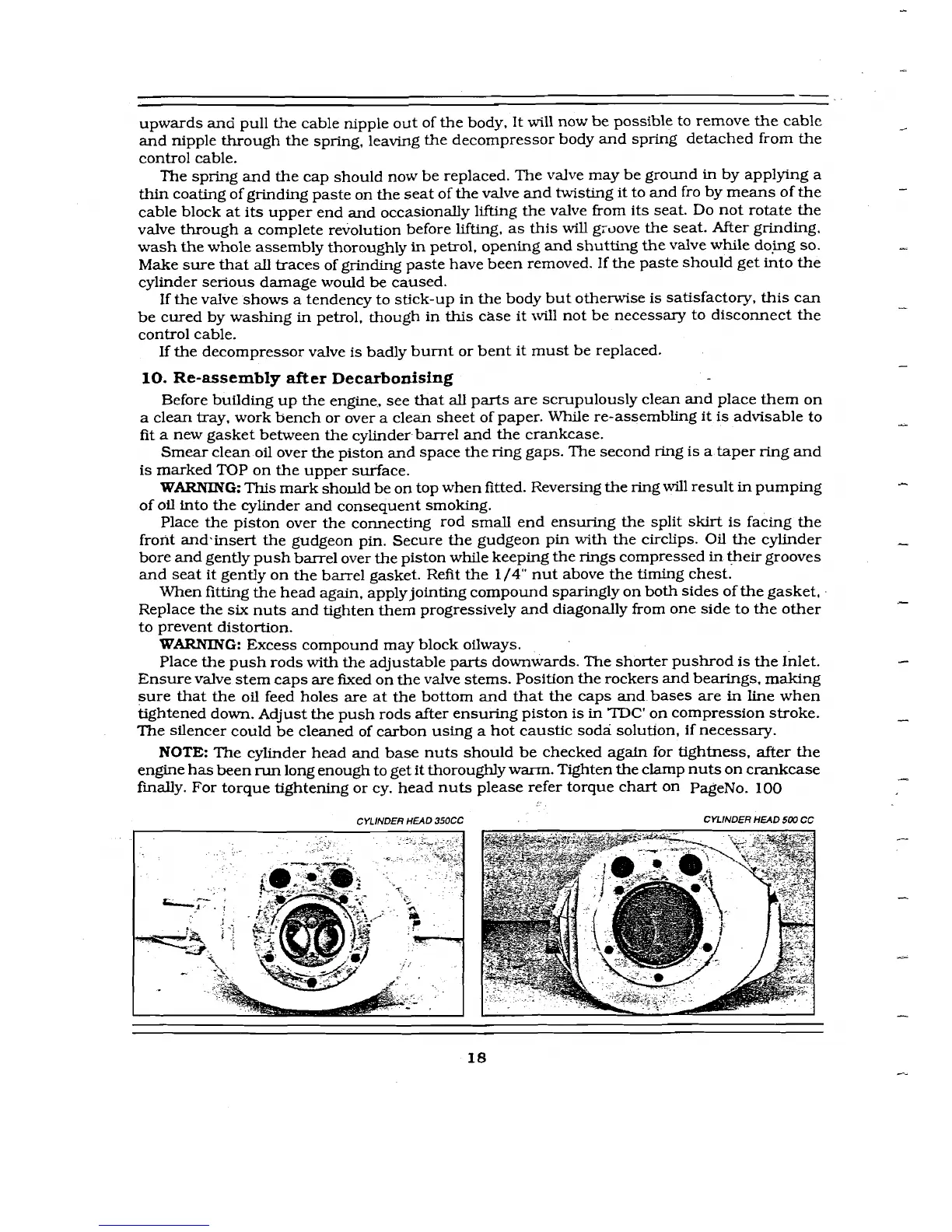
CYLINDER HEAD 350CC
CYLINDER HEAD
SW
CC
 Loading...