RG-ES206GS-P Series Switches Hardware Installation and Reference Guide Installing the switch
14
power cord is securely inserted into the device, fasten the power cord with power cord retention clips.
Do not place anything on the top of the switch.
Maintain a minimum clearance of 100 mm (3.94 in.) around the device to ensure proper airflow. Do not stack
switches.
Keep the switch away from high-power radio launch pads, radar launch pads, and high-frequency
large-current devices. Take electromagnetic shielding measures to minimize interference when necessary,
for example, use shielded interface cables.
Manage Ethernet cables with a distance of 100 meters (328.08 feet) indoors. Take lightning protection
measures if they need to be routed outdoors.
3.3.1 Installing the Switch in a Rack
RG-ES205C-P, RG-ES205GC-P, RG-ES209C-P, RG-ES209GC-P, RG-ES205GC, RG-ES208GC,
RG-ES206GC-P, RG-ES206GS-P, RG-ES210GS-P, and RG-ES210GC-LP cannot be installed in a cabinet.
RG-ES218GC-P, RG-ES226GC-P, RG-ES224GC and RG-ES216GC meet the EIA standard, and can be
installed in a 19-inch rack. The installation steps are as follows:
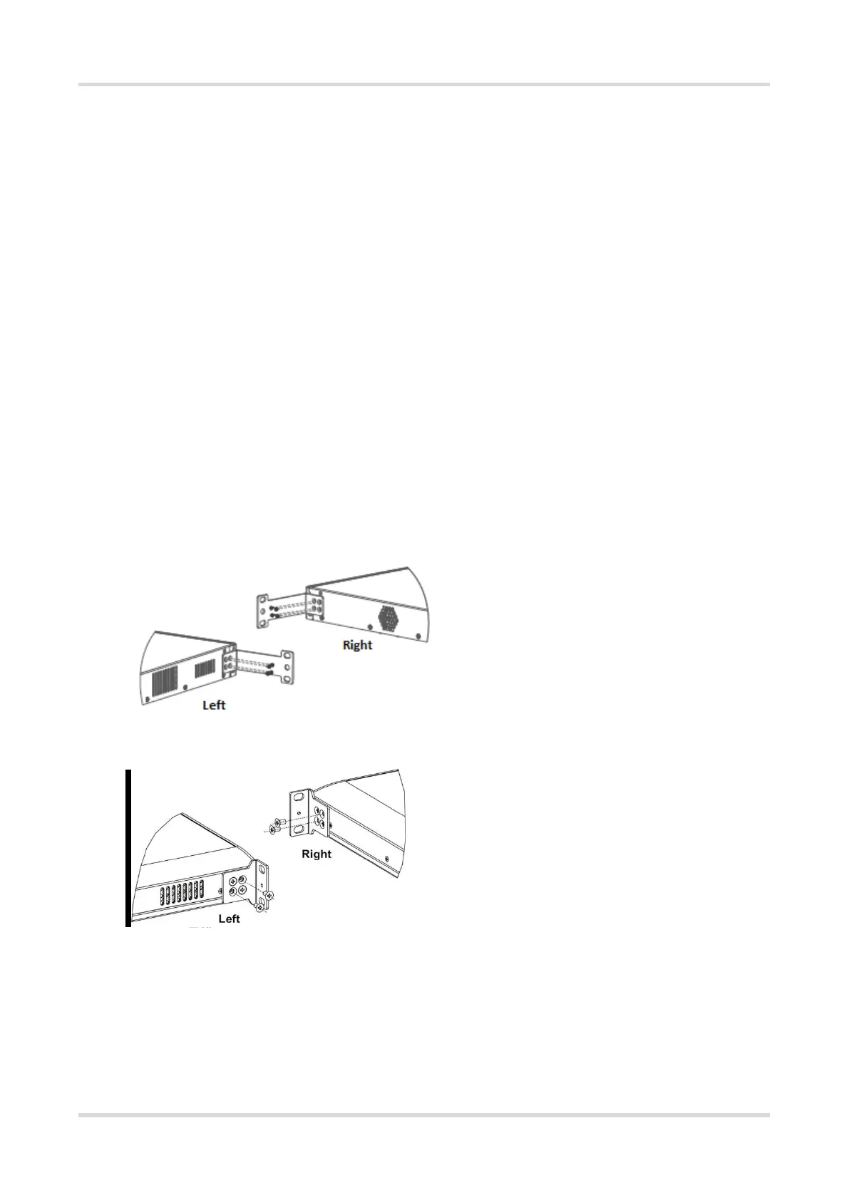
Step 1: Take screws out of the mounting bracket package and install one end of the mounting brackets to the
switch, as shown in Figure 3-1.
Figure 3-1 Securing Mounting Brackets
Figure 3-2 Securing Mounting Brackets
 Loading...