RG-ES206GS-P Series Switches Hardware Installation and Reference Guide Installing the switch
16
3.3.2 Mounting the Switch on the Wall
RG-ES206GS-P, RG-ES210GS-P, RG-ES209C-P, RG-ES209GC-P, RG-ES205GC (only can be mounted
vertically), RG-ES208GC, RG-ES206GC-P, and RG-ES210GC-LP can be mounted on a wall. (Screws and wall
anchors for installation are not provided, and needs to be purchased by the customer).
When installing the switch, drill two holes on the wall based on the size and depth of the screws and wall
anchors. Make sure that the holes are large enough to accommodate the wall anchor, with only the outer edge
visible outside the wall. Additionally, ensure that the screws can be firmly fastened to the wall.
Taking RG-ES209GC-P as an example, the specific steps for mounting the switch on the wall are as follows:
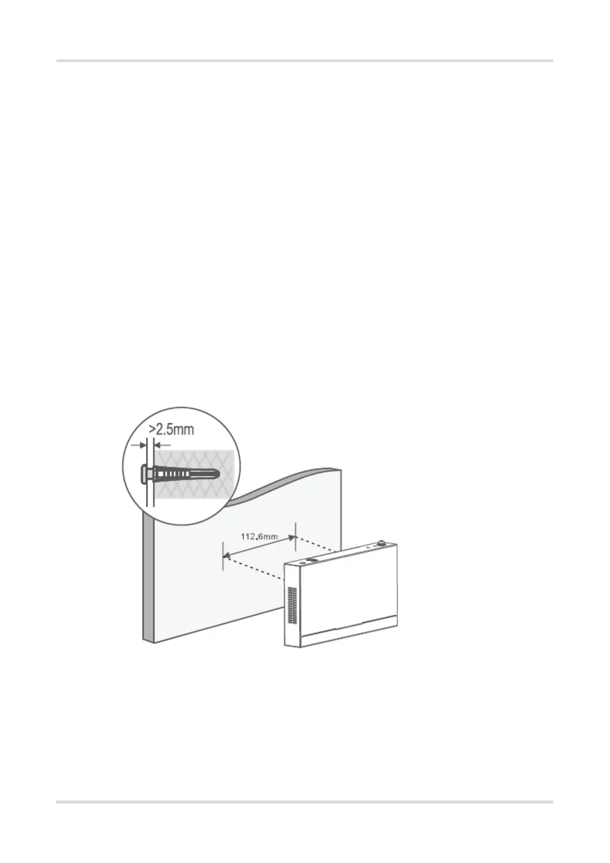
Step 1. As shown in the following figure, first drill two holes with a diameter of about 5mm on the wall, with a
spacing of 112mm between the two holes. Make sure that the two holes are horizontally aligned.
Step 2. Insert one wall anchor into each hole. Make sure the outer edge of the wall anchor is level with the wall
surface.
Step 3. Inset one M4 screw (length > 12mm) into each wall anchor. Leave a clearance of 2.5 mm (0.10 in.) to
3.5 mm (0.14 in.) between the base of the screw head and the wall anchor so the switch can hang on the
screws securely.
Step 4. Align the two holes on the chassis with the screws, and hang the switch securely on the screws.
Figure 3-6 Mount the Switch on the Wall
Note: When the device is mounted on a wall, it is only suitable to be mounted on a concrete or non-flammable
surface.
3.3.3 Installing the Switch on a Workbench
In some cases, if a standard 19-inch rack is unavailable, the switch can be mounted on a clean workbench, as
shown in Figure 3-7. The location where the switch is installed must be subject to movement restrictions.
 Loading...