PCB Diagram _ 71
6. PCB DIAGRAM
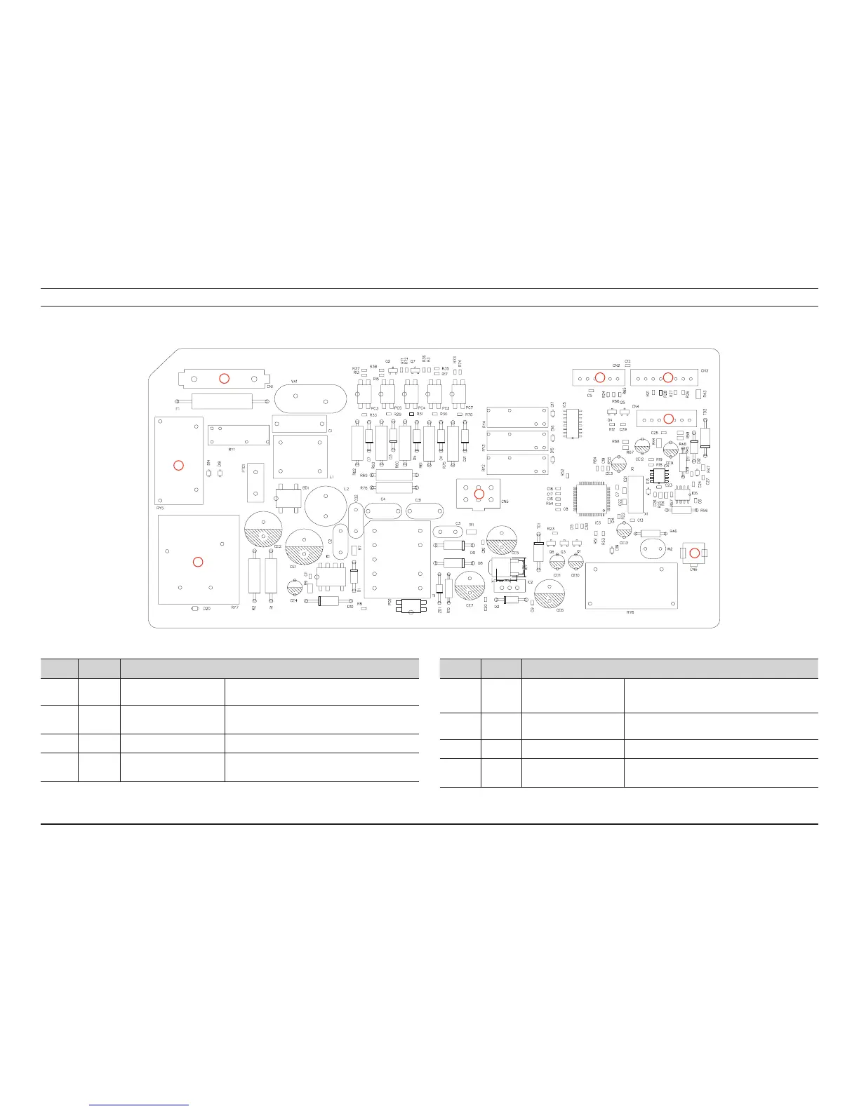
6-1. MAIN PCB
Location Part No. Function
1 CN1
AC CONNECTION
CONNECTOR
SuppliesACpowertothePBA
2 CN2
SUB PBA COMMUNICATION
CONNECTOR
TheconnectorthatcontrolscommunicationswiththeSubPBA
correspondingtotheDisplay.
3 CN3 MICOM FLASH CONNECTOR TheconnectorthatwritessoftwareontotheMICOM.
4 CN4
SENSOR CONNECTION
CONNECTOR
Connectsthetemperaturesensorinordertodetectthe
temperatureoftheheater.
Location Part No. Function
5 CN5
VALVECONNECTION
CONNECTOR
(SteamModelsOnly)
ItisconnectedtothesteamValve(SteamModelsOnly)andthe
LampoftheDriveBlockandcontrolstheON/OFFsignal.
6 CN6
SET GROUND CONNECTION
CONNECTOR
TheconnectorconnectingtheDryerSetandthegroundofthe
PBA
7 RY5 MOTOR OPERATION RELAY TherelaythatturnstheMainMotorandoff.
8 RY7
HEATER1 OPERATION RELAY
TherelaythatturnstheHeater1onandoff.
1
2 3
4
7
5
6
8
 Loading...