Construction
E - 14
Remote
control
Separately
sold item
Remote
control
Separately
sold item
Remote
control
Separately
sold item
Grounding
Grounding
GroundingGroundingGrounding
Grounding
Grounding
Indoor unit Indoor unit Indoor unit Indoor unit
Outdoor unit
Indoor unit
Remote control
wiring
Indoor/outdoor
operation cable
Earth leakage
breaker
Earth leakage
breaker
(Maximum 8 units can be connected)
Bus system cable for group control
Central control device
Maximum
20 units
(3) Electrical cabling system diagram
For electrical cabling installation, refer to the electrical
cabling system below, as well as the outdoor unit cable
diagram and the indoor unit circuit diagram.
1Multi-type system for buildings
■Cabling method
There are two types of power terminal board for indoor units, 7P and 5P+2P. The following basic cabling
diagram is drawn using the 5P+2P terminal board, so there are terminal boards that are different from those
shown in the illustration.
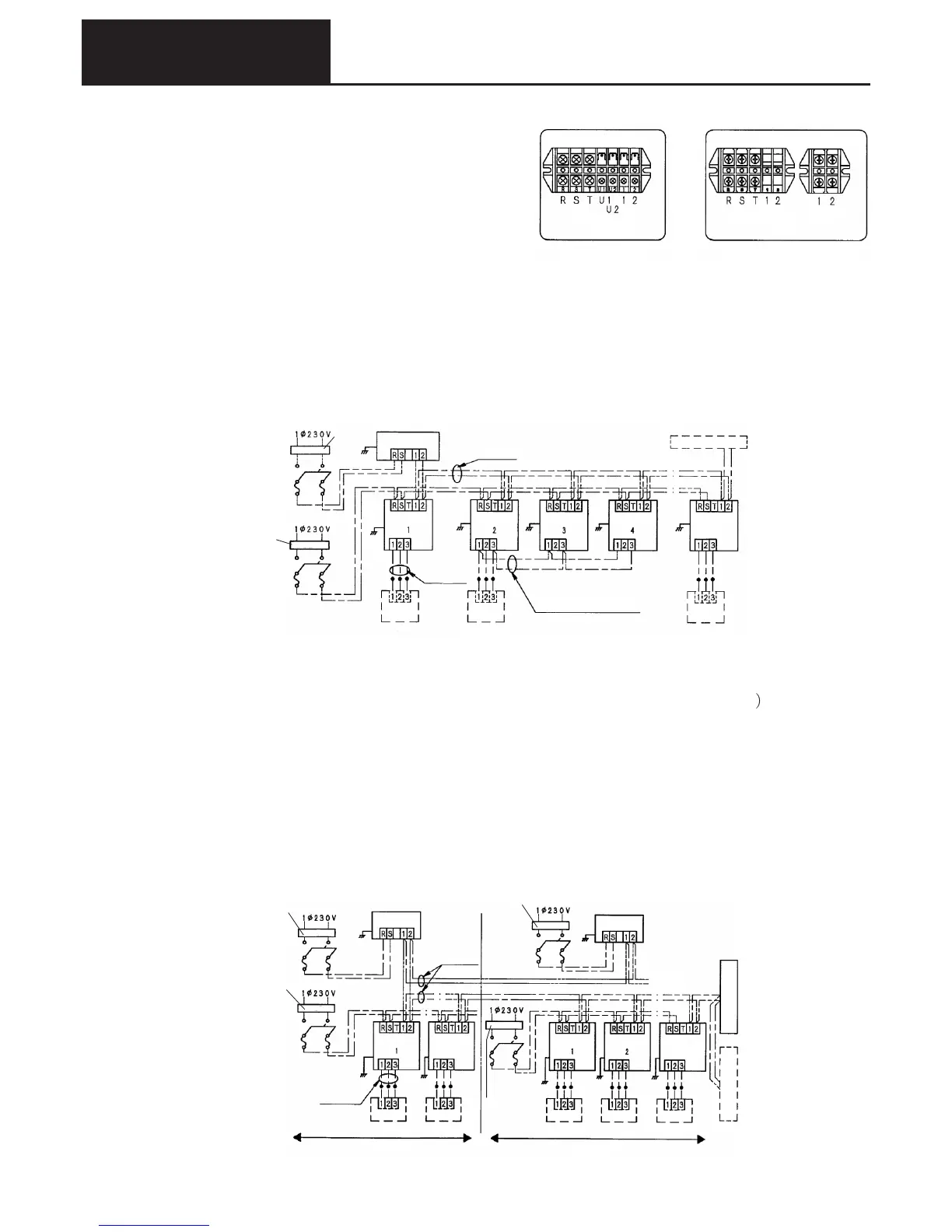
Arrangement for a one refrigeration system
Note 1) When a centralized control device is used, the signal cable from the centralized control device should
be connected to be the same signal cable as the indoor/outdoor operation cable. (no polarity)
Note 2) S7 on the outdoor unit board (terminal resistance ON/OFF switch) should be set to the ON side (when
shipped from the factory it is set to ON).
When the centralized control device controls indoor units on several refrigeration systems
Note 1) The power supply cabling for the indoor units should be carried out for each separate refrigeration
system. (If this cannot be done then use the bus system or the relay at a pull box.
Also, power cabling for outdoor units should be separate for each outdoor unit.
Note 2) The signal cable from the centralized control device should be connected to be the same signal cable
as the indoor/outdoor operation cable. (no polarity)
Note 3) The maximum number of units that can be connected to the same signal cable is 64 indoor units,
and 30 outdoor units.
Note 4) If the indoor/outdoor operation cable is connected in a loop then communication is not possible.
Therefore, do not connect in a loop.
Note 5) On the common communication cable (indoor/outdoor operation cable) outdoor unit board
S7(terminal resistance ON/OFF switch), all units save one should be set to the OFF side (when
shipped from the factory they are set to ON).
5P+2P terminal board model7P terminal board model
5P terminal board 2P terminal board
Power
source
Indoor/
outdoor
operation
cable
Remote
control
Power
source
Indoor/
outdoor
operation
cable
Remote
control
7P terminal board
3. Points regarding electrical construction (indoor unit)
Same refrigerant system Same refrigerant system
Remote
control
Separately
sold item
Remote
control
Separately
sold item
Remote
control
Separately
sold item
Remote
control
Separately
sold item
Remote
control
Separately
sold item
Indoor unitIndoor unit
Indoor unit
Outdoor
unit 2
Outdoor
unit 1
Indoor unit
Indoor unit
Maximum
20 units
Maximum
20 units
To other systems
Central control devi
ce A
Central control devi
ce B
Grounding
GroundingGrounding
Grounding Grounding
Grounding
Grounding
Earth leakage breaker
Earth leakage breaker
Earth leakage
breaker
Earth leakage breaker
Indoor/outdoor
operation cable
Remote
control
wiring
 Loading...