Water heat exchange unit
H - 24
8.
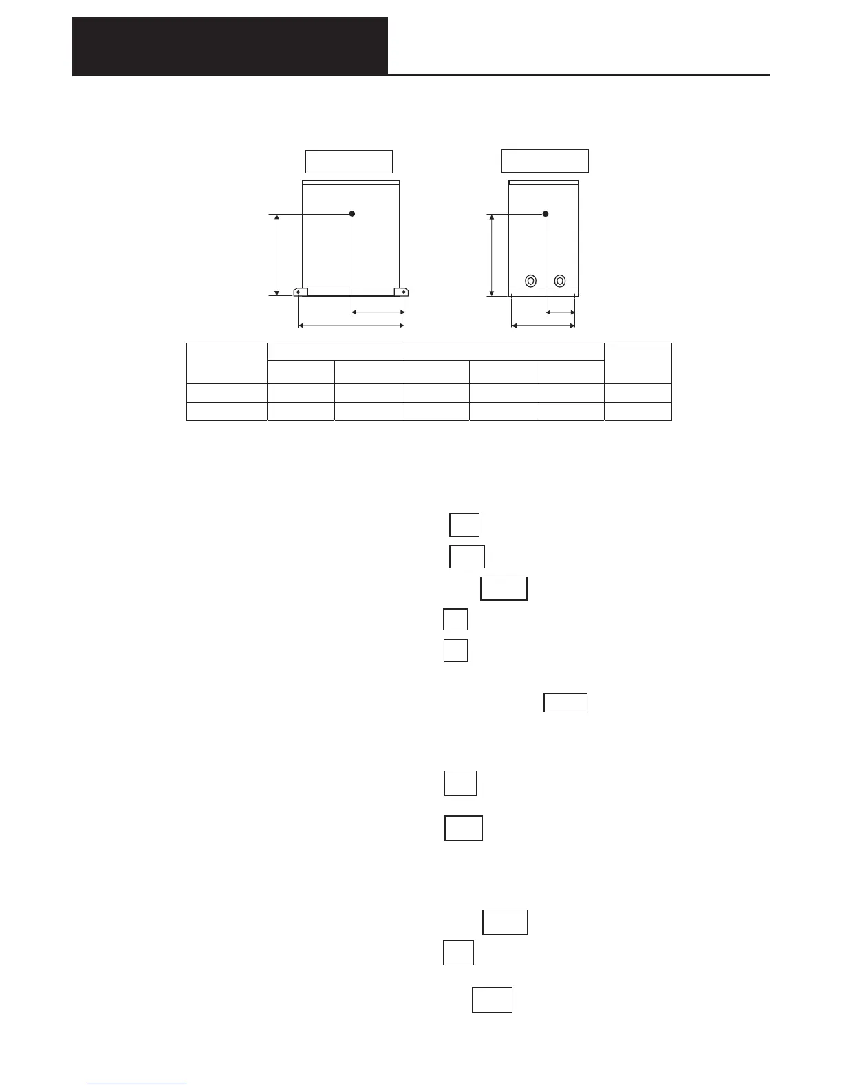
Position of center of gravity and earthquake resistance calculation
(1) Installation fixing position and center of gravity position
1Position of center of gravity
2Anchor bolt calculations
●Evaluation by calculation
Foundation bolt conditions
Total no. of bolts(N
)
N =㩷㩷 4㩷
No.
No.
No.
………..current models have 4 bolts
bolt diameter(D
)
D =㩷㩷 10 mm ………..for M10 bolts
bolt cross-sectional area(A
)
A = D
2
/4 =㩷 79 mm
2
bolts on one side䋺short direction(n
1
)
n
1
=㩷 2㩷㩷 ………..current models have 2 bolts
㩷㩷㩷㩷㩷㩷 long direction(n
2
)
n
2
=㩷 2㩷㩷 ………..current models have 2 bolts
The installation method is “embedded J type, JA type bolts”, on a slab 15cm thick.
Foundation bolt allowable short term tensile load(T
a
)
T
a
=㩷 4,508㩷 N
(It is also acceptable to decide the installation method after completing the calculation
)
Calculation
Design horizontal magnitude(K
H
)
K
H
=㩷 1.0㩷㩷………..installation location:K
H
on roof: 1.0
㩷㩷㩷㩷㩷㩷㩷㩷㩷㩷㩷㩷㩷㩷㩷㩷㩷㩷㩷㩷㩷㩷㩷㩷㩷㩷㩷㩷㩷㩷㩷㩷㩷㩷㩷㩷㩷㩷㩷㩷㩷
㩷㩷on ground:0.4
Operating load(W
)
W =㩷㩷N
(=operating mass×9.8
)
Horizontal earthquake force(F
H
)
F
H
= K
H
䊶W=㩷㩷 N
N
㩷 Height of center of gravity(h
)
h
G
=㩷 mm
Vertical earthquake force(F
V
)
F
V
=F
H
/2=㩷
1
2
π
Position of fastenings Position of center of gravity
Outdoor unit
type
l
1
l
2
l
G 1
l
G 2
h
G
Product
mass
 Loading...