Design
D - 9
3. Refrigerant piping design
Intake pipe or thick
pipe (gas pipe)
90°elbow
45°elbow
Tees
Socket
U bend
(R60~100mm)
Trap bend
Branch pipe
Header pipe 1
Ball valve for service Not necessary to calculate an effective length
φφφφφφφφ
Effective length
R
d
45°bend 90°bend 180°bend
0.5 25.0×d 40.0×d
53.5×d
1.0 12.0×d 18.5×d
25.8×d
1.5 7.8×d 12.2×d 16.4×d
2.0 6.4×d 10.0×d 13.4×d
2.5 5.9×d 9.2×d 12.3×d
3.0 5.7×d 9.0×d 12.0×d
3.5 5.9×d 9.2×d 12.2×d
4.0 6.4×d 10.0×d 13.4×d
4.5 7.1×d 11.0×d 14.8×d
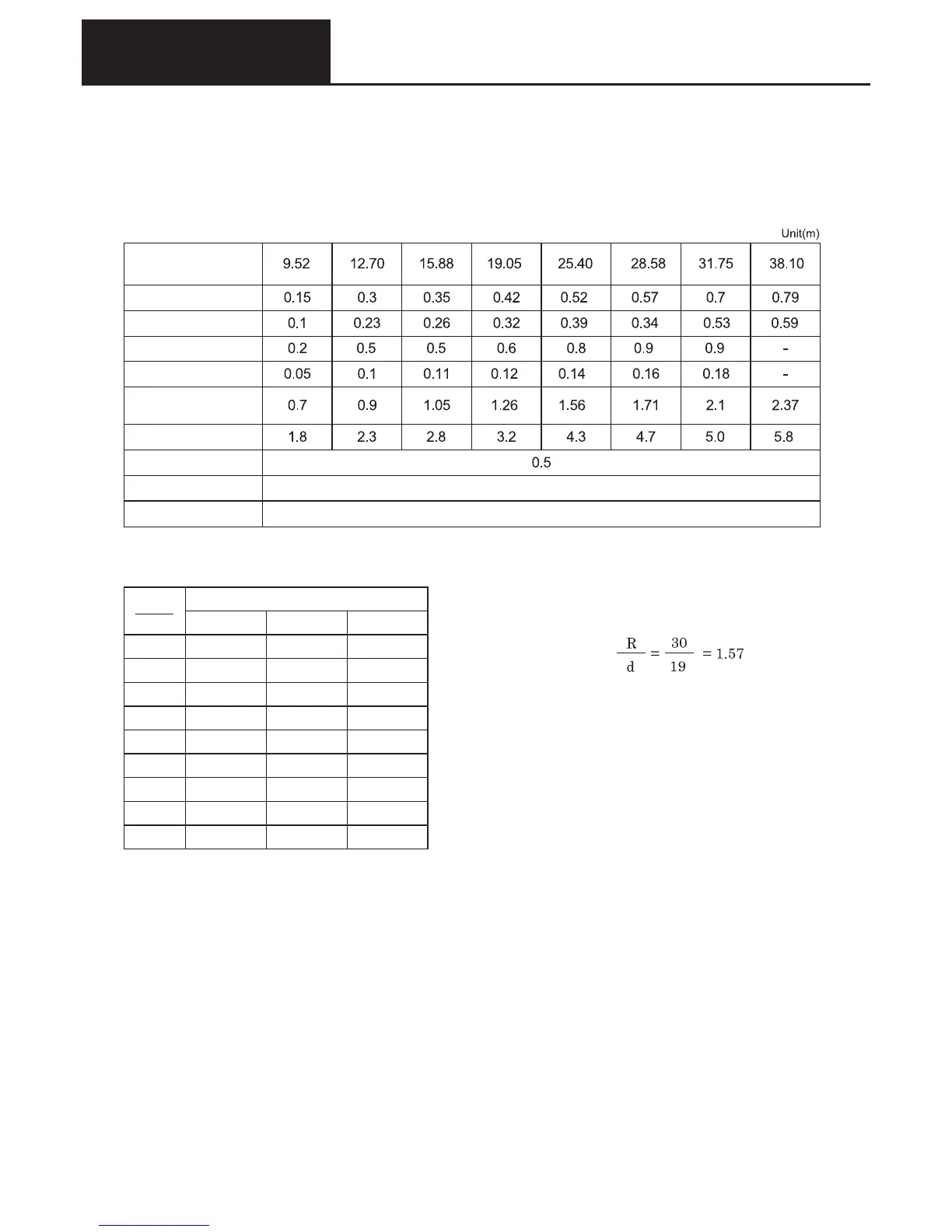
(4) Effective length of refrigerant piping
The effective straight length of the connectors used in the piping system is given in the table below. The piping system
design should be based upon this.
● Effective straight length of connectors (Table 3)
● Effective straight length of bent pipe (Table 4)
Calculation example
d: Outer diameter
R: Bend radius
(Example)
For a 19mm pipe bent through 90
o
on a 30mm radius (d=19, R=30)
from the table
length = 12.2 x 19 = 231mm
0.23 is the result.
 Loading...