Water heat exchange unit
H - 19
6. Installation construction
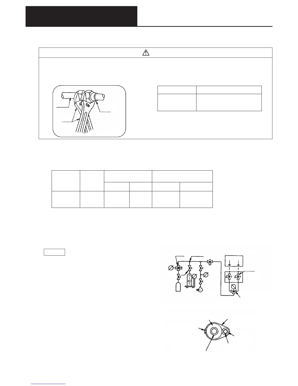
Caution
When removing or tightening the flare nut of the refrigerant connector, be sure to use a double spanner, and
apply the appropriate torque. If damage or loosening of the flare portion occurs, this can result in leakage of
refrigerant and could cause a suffocation accident.
(2) Refrigerant piping construction
Pipe diameter Tightening torque (N, m)
φ
19.05(3/4’’)
100 ~ 120
Figure 4
Connected
pipe
Spanner
Pipe connector
1 Lay the pipes so that the length of piping is as short as possible, and the difference in high and low points is minimized.
Also, when bending pipes, do not break them.
2 The limitations on refrigerant pipe length between the water heat exchanger unit and the outdoor unit, and the difference
in height between the high and low points are shown in Table 2. When installing, it is necessary to provide additional
refrigerant charge for the length of the refrigerant pipes.
Allowable difference in high
and low points
Refrigerant pipe (copper pipe C1220T
Outer diameter×thickness mm)
Refrigerant
additional
charge quantity
Allowable
pipe length
Outdoor unit
is higher
Outdoor unit
is lower
Liquid side Gas side
280g/m
120m
(effective
length 145m)
50m *35m 19.05×1.0 38.1×1.8
* For cooling operation when the outdoor air temperature is 10oC or less, this value should be 30m.
3 Do not allow dust, dirt, or moisture to become trapped inside the piping.
4 After connecting the piping, carry out a gas tightness test by means of an air purge (Figure 5)
It is a legal obligation to carry out a leak test in accordance with the High Pressure Gas Safety Law. Therefore, after
connecting the pipes, carry out the test in accordance with the points below, to confirm that there are no leaks from the
joints. Subsequently fill in the form inside the outdoor unit (details of high pressure gas manufacturing facility, etc.).
Pressure
reducing
valve
Pressure
gage
Nitrogen
Three-way
fitting
Vacuum
gage
Vacuum
pump
(water heat
exchanger unit)
Closed
valve
(outdoor unit)
Gage manifold
Figure 5
Weighing
scales
Thermal insulation
(resistant to at least 120
o
C)
Indoor/outdoor operation cable
Wrap with decorative tape,
so that it does not come into
contact with the thin pipe
Thick pipe
(gas pipe)
Thin pipe (liquid pipe)
Decorative tape
(to prevent ingress of rainwater)
Figure 6
Thermal insulation
Cautions
1) Gas pressure in the gas tightness test : F3.0MPa
(If the outdoor unit is H1 type, then the
pressure is 2.74MPa)
2) After the gas tightness test, carry out vacuum suction down
to 667Pa.
3) Do not open the closed outdoor unit valves until the gas
tightness and vacuum suction tests are complete.
5 Apply thermal insulation to the piping.
●●
●●
● Apply the thermal insulation after completing the leak
check on the pipe joints.
●●
●●
● Apply thermal insulation to both the thick pipes and
thin pipes.
6 A gas heat pump air conditioning system must be installed
in accordance with the “High pressure gas safety law”, the
“Refrigeration safety regulations”, the “Criteria for
refrigeration installations” published by the High Pressure
Gas Safety Institute of Japan, and all the necessary
reporting procedures must be carried out.
 Loading...