EasyManuals Logo
Home>Scully>Control Unit>ST-47 Series

Scully ST-47 Series User Manual

Scully ST-47 Series
40 pages
To Next Page IconTo Next Page
To Previous Page IconTo Previous Page
Page #19 background imageLoading...
Page #19 background image
Self-Proving Vehicle Grounding Verication System
Diagram Appendix
Page 19.
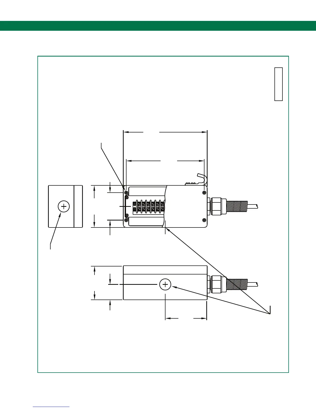
6.3 DWG 63039 – Outline Drawing – Sculcon Junction Box
63039 RevF
7.33
7.87
(200.0)
5 63 42
(186.2)
3.94
(100.0)
CONDUIT HUB (CABLE GLAND)
Ø1.06 (27) KNOCKOUT FOR
1
3.94
(65.5)
2.58
(100.0)
(81.3)
3.20
1.44
(36.6)
Ø1.06 (27) HOLE FOR
CONDUIT HUB (CABLE GLAND)
MOUNTING CENTERS FOR
#8 (4) HEX SOCKET
HEAD SCREWS (4 PLACES)
NOTES:
1. DIMENSIONS ARE IN INCHES WITH
MILLIMETERS IN PARENTHIESS.

Table of Contents

Questions and Answers:

Question and Answer IconNeed help?

Do you have a question about the Scully ST-47 Series and is the answer not in the manual?

Scully ST-47 Series Specifications

General IconGeneral
BrandScully
ModelST-47 Series
CategoryControl Unit
LanguageEnglish