TEST PROCEDURES (CONT’D)
PROCEDURE
NUMBER
COMPONENTTEST
3
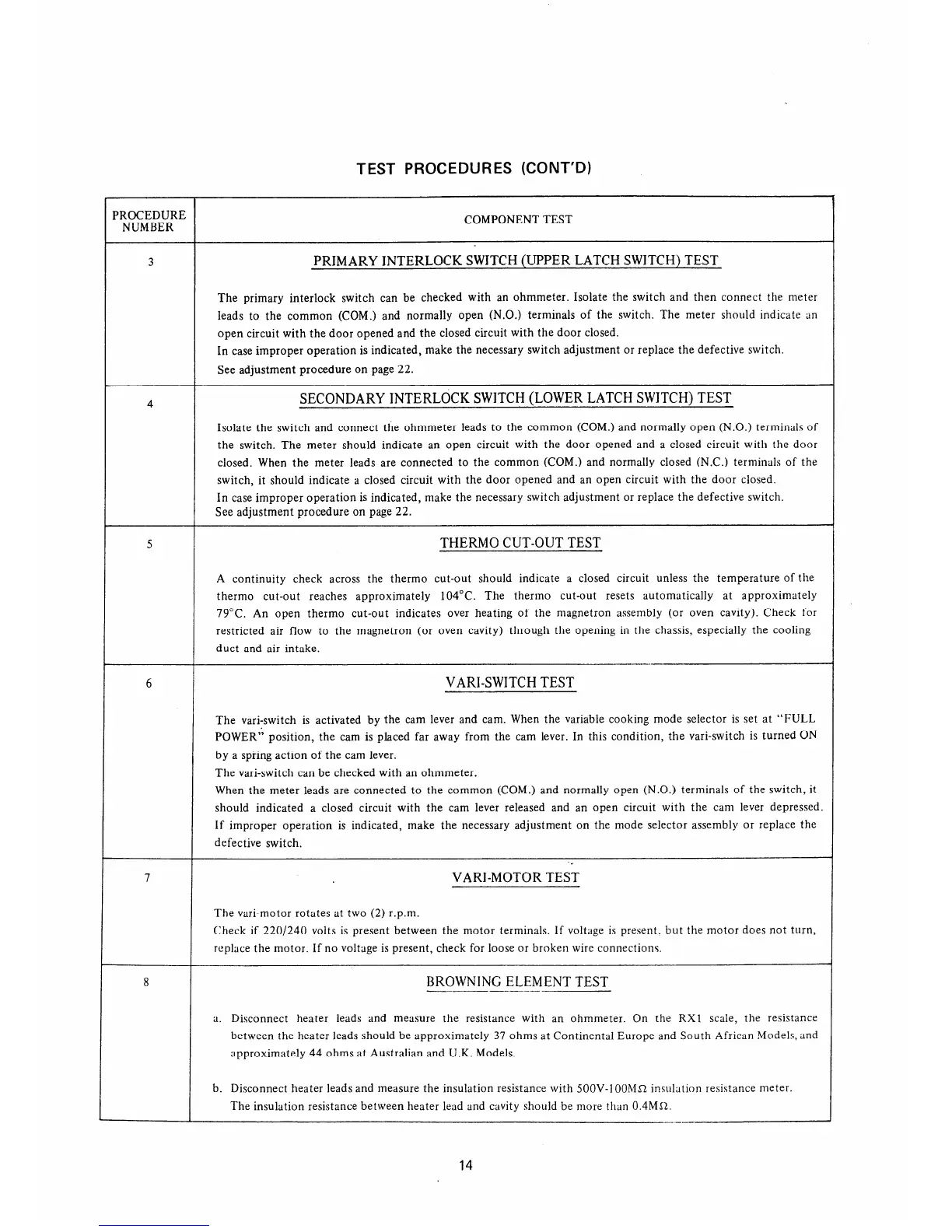
PRIMARYINTERLOCKSWTTCH(UPPERLATCHSWITCH)TEST
The primary interlock switch can be checked with an ohmmeter. Isolate the switch and then connect the meter
leads to the common (COM.) and normally open (N.O.) terminals of the switch. The meter should indicate an
open circuit with the door opened and the closed circuit with the door closed.
In case improper operation is indicated, make the necessary switch adjustment or replace the defective switch.
See adjustment procedure on page 22.
4
SECONDARYINTERLOCKSWITCH(LOWERLATCHSWJTCH)TEST
Isolate the switch and connect the ohmmeter leads to the common (COM.) and normally open (N.O.) terminals of
the switch. The meter should indicate an open circuit with the door opened and a closed circuit with the door
closed. When the meter leads are connected to the common (COM.) and normally closed (N.C.) terminals of the
switch, it should indicate a closed circuit with the door opened and an open circuit with the door closed.
In case improper operation is indicated, make the necessary switch adjustment or replace the defective switch.
See adjustment procedure on page 22.
5
THERMOCUT-OUTTEST
A continuity check across the therm0 cut-out should indicate a closed circuit unless the temperature of the
therm0 cut-out reaches approximately 104°C. The therm0 cut-out resets automatically at approximately
79°C. An open therm0 cut-out indicates over heating of the magnetron assembly (or oven cavity). Check for
restricted air flow to the magnetron (or oven cavity) through the opening in the chassis, especially the cooling
duct and air intake.
6
7
VARI-SWITCHTEST
The vari-switch is activated by the cam lever and cam. When the variable cooking mode selector is set at “FULL
POWER” position, the cam is placed far away from the cam lever. In this condition, the vari-switch is turned ON
by a spring action of the cam lever.
The vari-switch can be checked with an ohmmeter.
When the meter leads are connected to the common (COM.) and normally open (N.O.) terminals of the switch, it
should indicated a closed circuit with the cam lever released and an open circuit with the cam lever depressed.
If improper operation is indicated, make the necessary adjustment on the mode selector assembly or replace the
defective switch.
-<
VARI-MOTORTEST
The vari-motor rotates at two (2) r.p.m.
Check if 220/240 volts is present between the motor terminals. If voltage is present. but the motor does not turn,
replace the motor. If no voltage is present, check for loose or broken wire connections.
8
BROWNINGELEMENTTEST
--
-__-_
a. Disconnect heater leads and measure the resistance with an ohmmeter. On the RX1 scale, the resistance
between the heater leads should be approximately 37 ohms at Continental Europe and South African Models, and
approximately 44 ohms at Australian and U.K. Models.
b. Disconnect heater leads and measure the insulation resistance with 5OOV-1 OOMR insulation resistance meter.
The insulation resistance between heater lead and cavity should be more than 0.4MJ2.
--
14
 Loading...