Part of
Lock Device
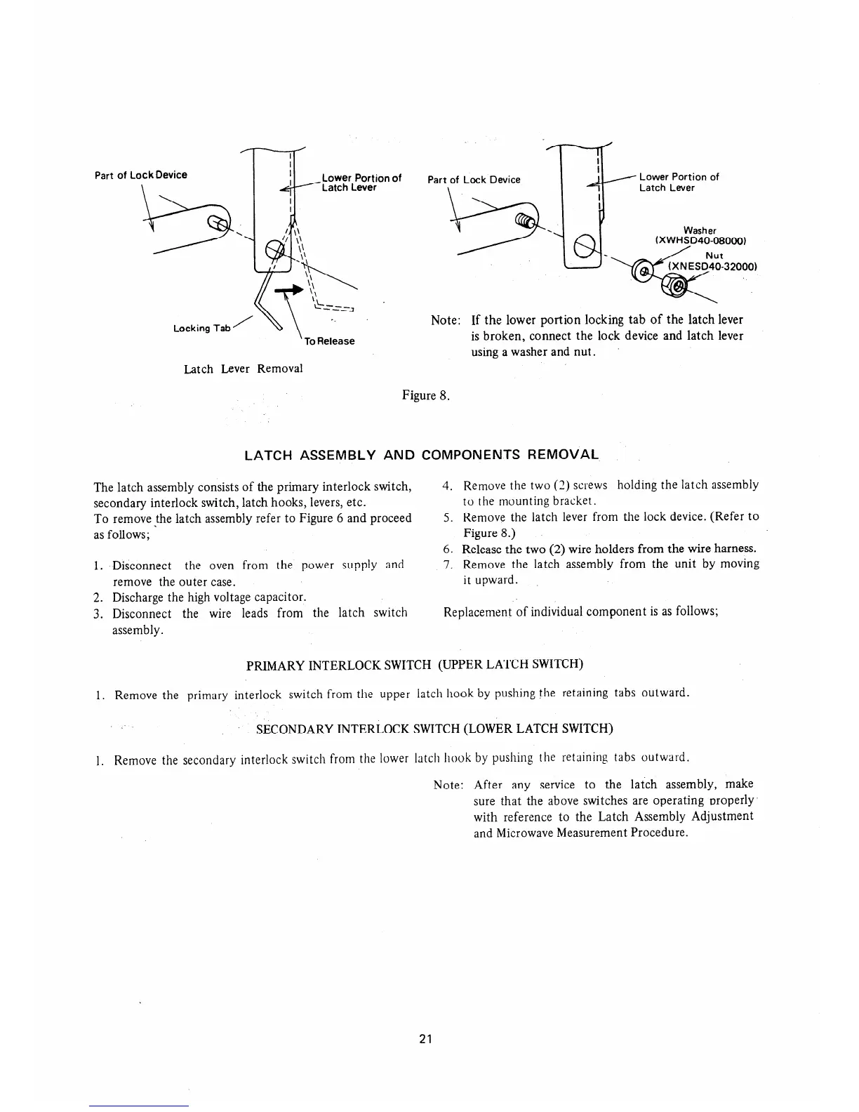
Latch Lever Removal
I
I
Part of Lock Device
Lower Portion of
Washer
(XWHSD40-08000)
32000)
Note: If the lower portion locking tab of the latch lever
is broken, connect the lock device and latch lever
using a washer and nut.
Figure 8.
LATCH ASSEMBLY AND COMPONENTS REMOVAL
The latch assembly consists of the primary interlock switch,
secondary interlock switch, latch hooks, levers, etc.
To remove the latch assembly refer to Figure 6 and proceed
as folIows;
1. Disconnect the oven from the power supply and
remove the outer case.
2. Discharge the high voltage capacitor.
3. Disconnect the wire leads from the latch switch
assembly.
4. Remove the two (2) screws holding the latch assembly
to the mounting bracket.
5. Remove the latch lever from the lock device. (Refer to
Figure 8.)
6. Release the two (2) wire holders from the wire harness.
7. Remove the latch assembly from the unit by moving
it upward.
Replacement of individual component is as follows;
PRIMARY INTERLOCK SWITCH (UPPER LATCH SWITCH)
1. Remove the primary interlock switch from the upper latch hook by pushing the retaining tabs outward.
SECONDARY INTERLOCK SWITCH (LOWER LATCH SWITCH)
1. Remove the secondary interlock switch from the lower latch hook by pushing the retaining tabs outward.
Note: After any service to the latch assembly, make
sure that the above switches are operating nroperly
with reference to the Latch Assembly Adjustment
and Microwave Measurement Procedure.
21
 Loading...