DOOR REPLACEMENT AND ADJUSTMENT
DOOR REPLACEMENT
1. Disconnect the oven
from the power supply and
remove the outer case.
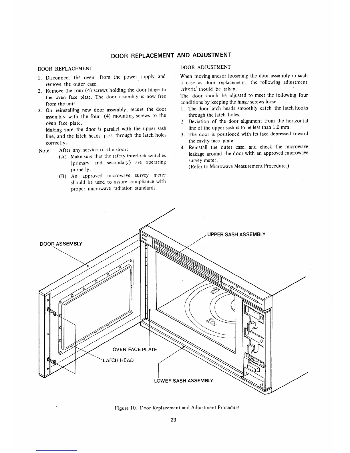
2. Remove the four (4) screws holding the door hinge to
the oven face plate. The door assembly is now free,
from the unit.
3. On reinstalling new door assembly, secure the door
assembly with the four (4) mounting screws to the
oven face plate.
Making sure the door is parallel with the upper sash
line, and the latch heads pass through the latch holes
correctly.
Note:
After any service to the door;
(A) Make sure that the safety interlock switches
(primary and secondary) are operating
properly.
(W An
approved
microwave survey meter
should be used to assure compliance with
proper microwave radiation standards.
DOOR ADJUSTMENT
When moving and/or loosening the door assembly in such
a case as door replacement, the following adjustment
criteria’ should be taken.
The door should be adjusted to meet the following four
conditions by keeping the hinge screws loose.
1. The door latch heads smoothly catch the latch hooks
through the latch holes.
2. Deviation of the door alignment from the horizontal
line of the upper sash is to be less than 1 .O mm.
3. The door is positioned with its face depressed toward
the cavity face plate.
4. Reinstall the outer case, and check the microwave
leakage around the door with an approved microwave
survey meter.
(Refer to Microwave Measurement Procedure.)
/UPPER
SASH ASSEMBLY
Figure 10. Door Replacement and Adjustment Procedure
23
 Loading...