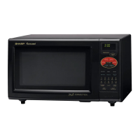
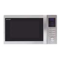
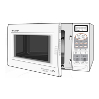
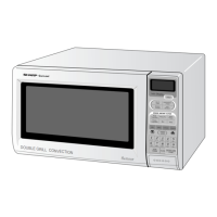
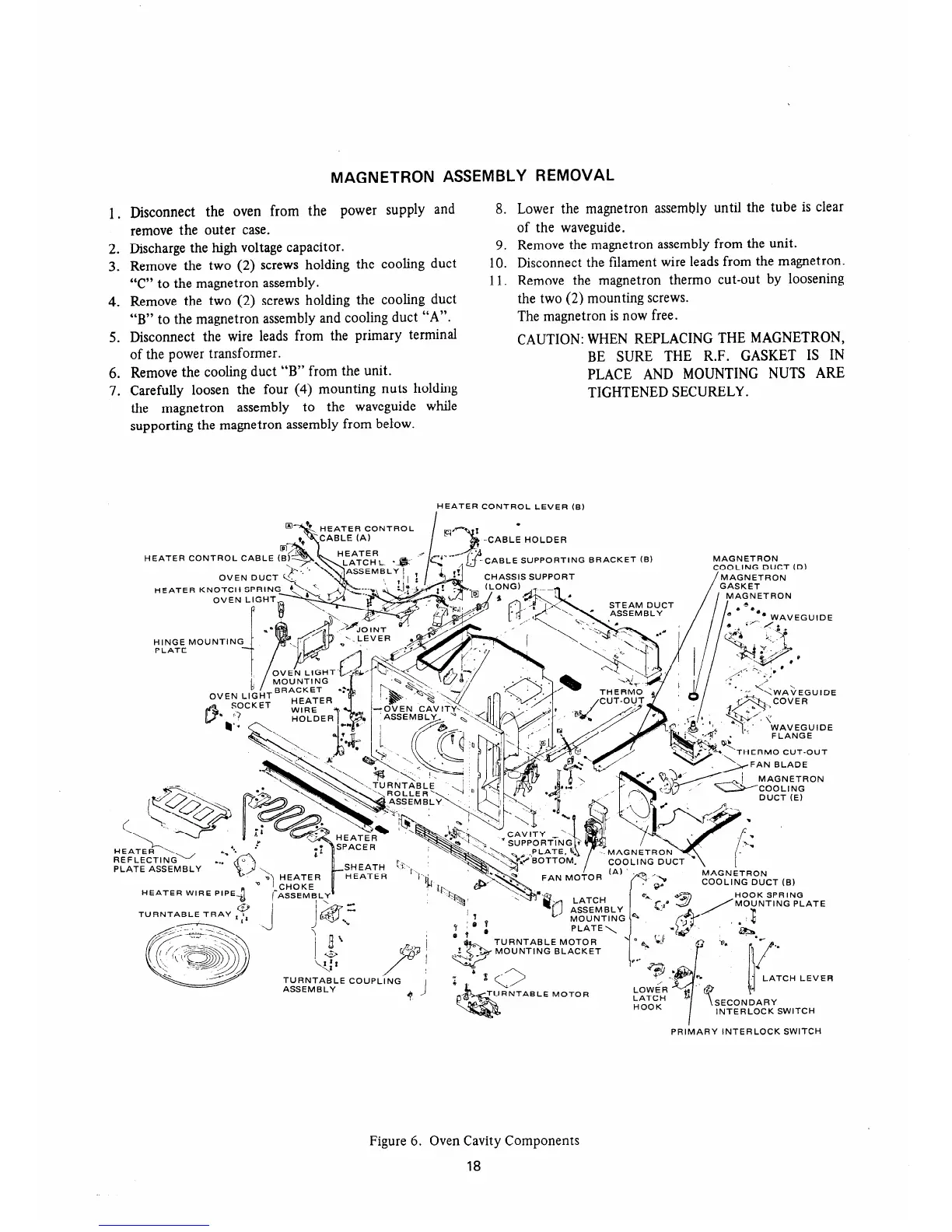
MAGNETRON ASSEMBLY REMOVAL
1. Disconnect the oven from the power supply and
remove the outer case.
2. Discharge the high voltage capacitor.
3. Remove the two (2) screws holding the cooling duct
“C” to the magnetron assembly.
4. Remove the two (2) screws holding the cooling duct
“B” to the magnetron assembly and cooling duct “A”.
5. Disconnect the wire leads from the primary terminal
of the power transformer.
6. Remove the cooling duct “B” from the unit.
7. Carefully loosen the four (4) mounting nuts holding
the magnetron
assembly to the waveguide while
supporting the magnetron assembly from below.
8. Lower the magnetron assembly until the tube is clear
of the waveguide.
9. Remove the magnetron assembly from the unit.
10. Disconnect the filament wire leads from the magnetron.
11. Remove the magnetron therm0 cut-out by loosening
the two (2) mounting screws.
The magnetron is now free.
CAUTION: WHEN REPLACING THE MAGNETRON,
BE SURE THE R.F. GASKET IS IN
PLACE AND MOUNTING NUTS ARE
TIGHTENED SECURELY.
HEATER CONTROL LEVER (B)
HEATER CONTROL CABLE (
OVEN DUCT
-CABLE HOLDER
CABLE SUPPORTING BRACKET (B)
S SUPPORT
FLANGE
TURNTABLE MOTOR
MOUNTING BLACKET
BLE MOTOR
SECONDARY
INTERLOCK SWITCH
PRlilARY INTERLOCK SWITCH
Figure 6. Oven Cavity Components
18
 Loading...