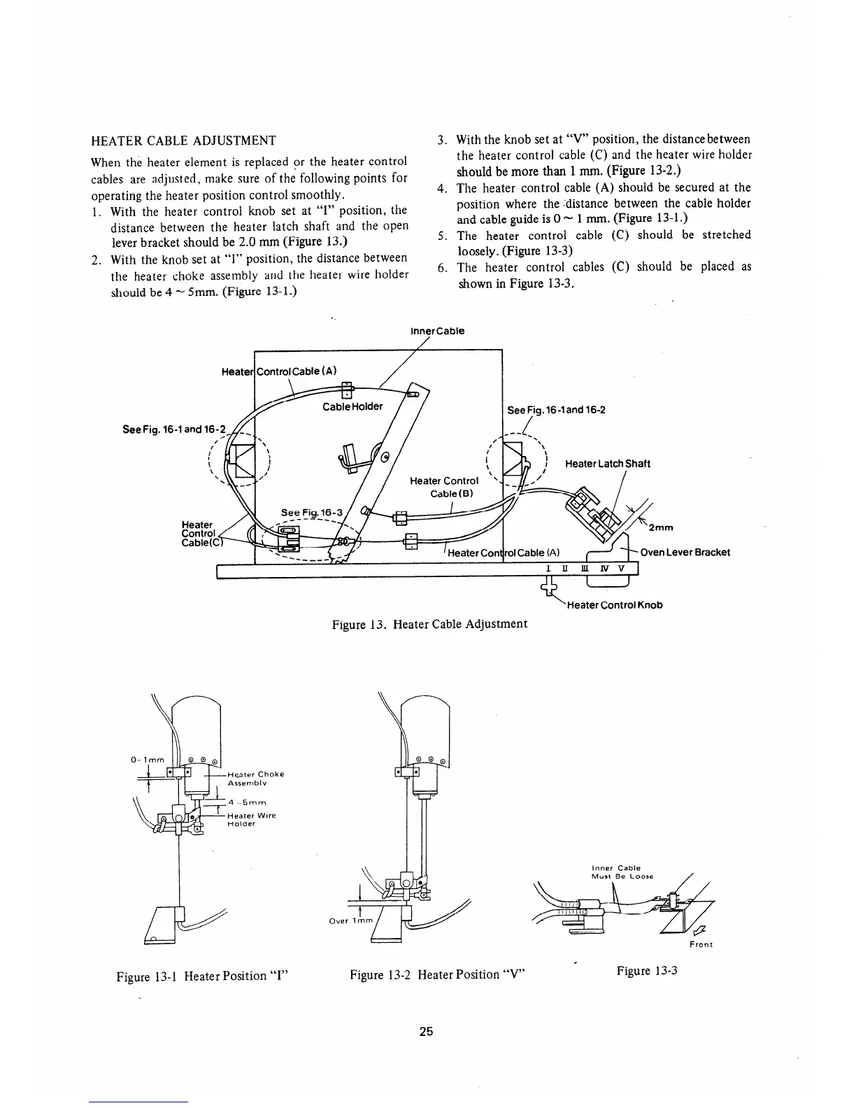
HEATER CABLE ADJUSTMENT
When the heater element is replaced or the heater control
cables are adjusted, make sure of the following points for
operating the heater position control smoothly.
3.
4.
1.
2.
With the heater control knob set at “I” position, the
distance between the heater latch shaft and the open
lever bracket should be 2.0 mm (Figure 13.)
With the knob set at “1” position, the distance between
the heater choke assembly and the heater wire holder
should be 4 - 5mm. (Figure 13- 1.)
5.
6.
See Fig.
With the knob set at “V” position, the distancebetween
the heater control cable (C) and the heater wire holder
should be more than 1 mm. (Figure 13-2.)
The heater control cable (A) should be secured at the
position where the .‘distance between the cable holder
and cable guide is 0
N 1 mm, (Figure 13-1.)
The heater control cable (C) should be stretched
loosely. (Figure 13-3)
The heater control cables (C) should be placed as
shown in Figure 13-3.
InnerCable
Heater
I
ControlCable (A)
/ I
16-1 and 16z~~‘--//
~,~l~~m’and lG2
I
J’
Heater Control Knob
Figure 13. Heater Cable Adjustment
Figure 13-1 Heater Position “I”
Figure 13-2 Heater Position 7”
25
Bracket
Inner Cable
Front
Figure 13-3
 Loading...