Assigning Transmitters to Transmitter Slots
Each receiver channel contains eight transmitter slots to control the RF signals
passed by the receiver. Transmitters can be assigned to the channel slots
or "registered" with the receiver.
For added protection from interference, the receiver will issue a warning or
block signals from any transmitters that aren't registered.
To assign a transmitter to a receiver channel:
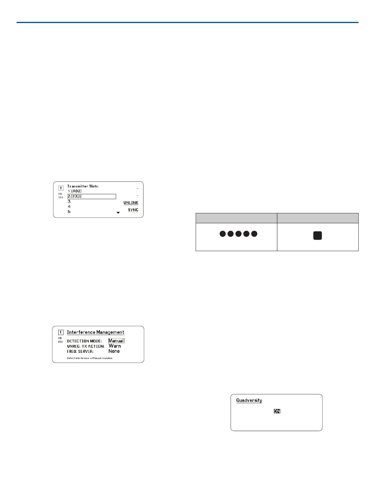
1. From the Channel menu: Transmitter(s)>Transmitter Slots
2. Use the control wheel to scroll to an available transmitter slot. If the slot
is occupied, syncing will overwrite the existing transmitter.
3. Align the transmitter with the IR sync window and press SYNC.
When the sync is complete, the transmitter will be assigned to the slot. The
transmitter will remain assigned to the slot until it is unlinked. To remove a
transmitter from a slot, use the control wheel to select the slot, and then press
UNLINK.
Tip: For quick access, the slots can be accessed from the channel menu by
selecting the F4 function button.
Interference Management
In the event of signal degradation, Interference Management technology
provides options to move to a clean, compatible frequency, either manually
or automatically.
Respond to an alert by manually selecting a new frequency, or allow the
Spectrum Manager or Wireless Workbench to automatically deploy a backup
frequency the instant interference is detected.
Tip: To dismiss a interference alert, select the affected channel, and then
select Dismiss.
Configuring Interference Management
Interference Management can be configured for each channel individually.
Setting the Detection Mode
The Mode setting determines how the receiver will switch to a clear frequency
in the event of interference
1. Select a channel and navigate to: Advanced>Interference Management
2. Choose one of the following modes:
⁃ Manual: Select a frequency manually when interference occurs
⁃ Automatic: Allow the receiver to automatically select a new frequency.
Unregistered Transmitter Action
The unregistered transmitter option determines how the receiver reacts to
the presence of unregistered transmitters, which can be a potential source
of interference.
From the Interference Management menu, choose one of the following op-
tions:
• Allow: The receiver will pass audio from the unregistered transmitter
• Warn: The receiver will display a warning when an unregistered transmit-
ter is detected
• Block: The receiver treat the unregistered transmitter as interference and
will block the audio
Frequency Server
The frequency server option allows you to assign a networked Spectrum
Manager as a server for clear frequencies in the event of interference.
1. From the Interference Management menu, select Freq. Server
2. Press the control wheel to enable editing, and then select a Spectrum
Manager from your network.
3. Press ENTER to save.
Channel Quality Meter
The home screen displays a channel quality meter, providing a visual indicator
of the RF signal-to-noise ratio. When the RF signal is strong with a low level
of noise, all five segments of the meter are filled or the number 5 is displayed.
If the noise floor increases, fewer segments are displayed or the quality
number drops. Low levels of channel quality provide an early warning of po-
tential problems, allowing you to switch to a clear frequency.
NumberSegment
Quadversity
Quadversity mode configures the receiver to accept four antenna inputs to
maximize RF coverage and minimize the risk of dropouts and signal loss
caused by interference. The receiver provides two channels of audio when
configured in Quadversity mode.
Configuring the Receiver and Antennas
In Quadversity mode, antennas are connected to RF connector ports and to
the RF cascade ports, which are converted to act as additional antenna inputs.
The receiver must be set to Quadversity to reconfigure the cascade ports.
1. From the Device Configuration menu: RF Device>Quadversity
2. Use to control wheel to set Quadversity to On. Press ENTER to reboot
the receiver and enable Quadversity mode.
3. Connect antennas to both RF antenna ports and to both RF cascade
ports.
4. Place the antenna in a pattern the provides coverage for your venue.
5. Perform a walk test to verify coverage and adjust the antenna positions
if necessary.
Antenna Bias
All antenna ports provide a DC bias to power active antennas. Set the DC
power to off when using passive (non-powered) antennas.
Shure IncorporatedAD4Q Digital Quad Receiver
2017/10/2512/21
 Loading...