SLEIPNER
SIDEPOWER
THRUSTERS
OFF
ON ON
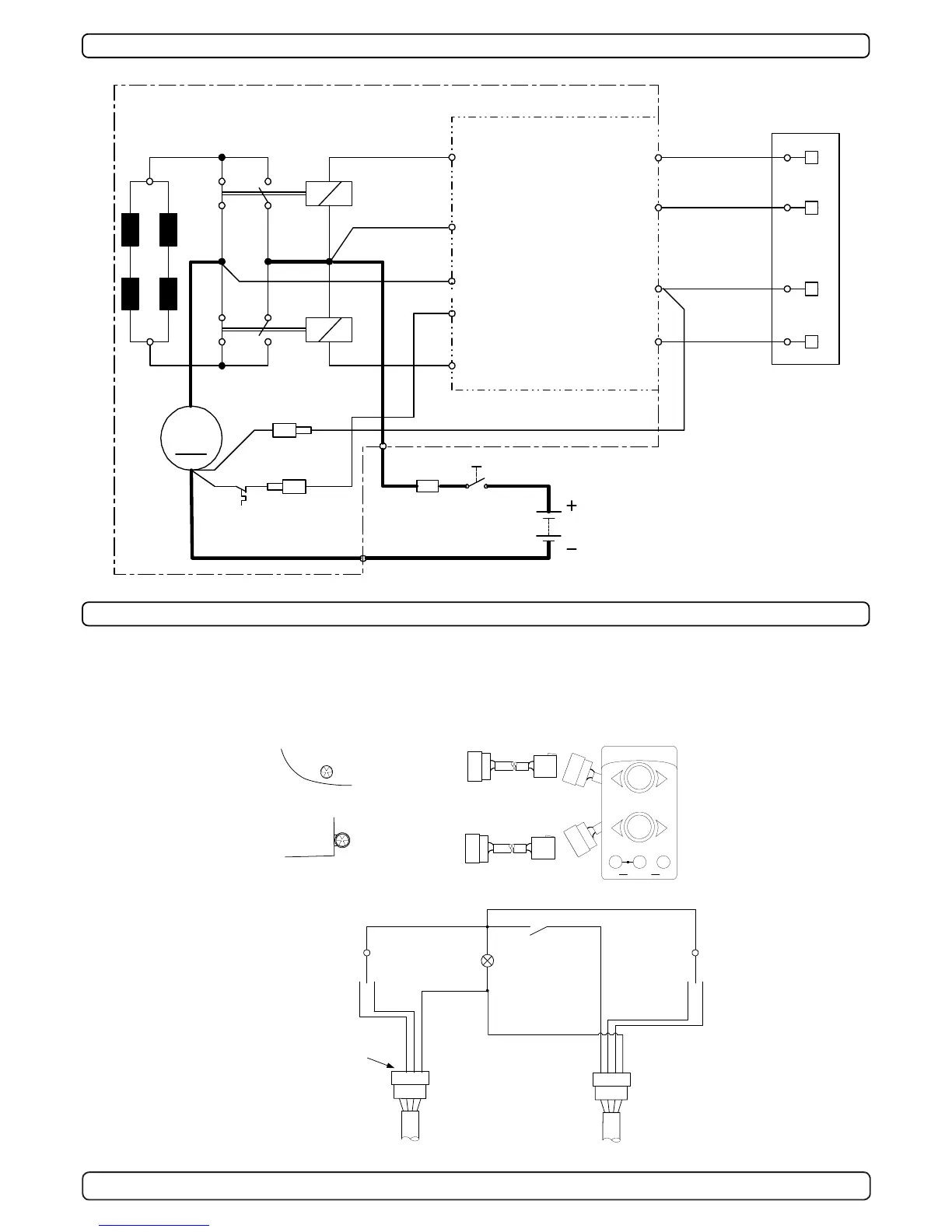
BOW
STERN
To sternthruster
To bowthruster
grey
blue
black
grey
blue
red
ON / OFF
System
Control
light
Joystick
for stern-
thruster
Joystick
for bow-
thruster
Positive lead from
sternthruster have been
removed in panel to
avoid current leakage
between different
battery banks if the
thrusters are powered
by different battery
banks.
Wiring diagram (simplified) for dual joystick panel
Visual connection diagram for dual joystick panel
y
We advice to use different battery banks for each thruster to ensure
maximum performance when both are used at the same time.
y
When using the original Sidepower control cables just connect them
to the corresponding joystick
y
There are no plus/positive power connected from the bowthruster
yellow
BOWSTERN
black
Technical wiring diagram
Electrical installation of stern thruster systems
M
Thermal
switch
Electronic
interface box
6 1230i
A2
A1
4 pin
AMP
connector
On Motor
4
2
1
3
Fuse
Battery
main
switch
1
5
4
2
6
8
9
red (+)
grey
(sig +)
blue
(sig +)
black (-)
red
grey
(sig -)
blue
(sig -)
brown
3red
Fused
inside 1A
black
7
white
 Loading...