Communication System Manual 3VF Circuit-Breakers
Copyright Siemens AG 1998. All rights reserved. Version1.0 (05/98)
12
2.1.4 Connecting 3VF to the communication system
1.) Check that all the system components are fitted
Check that all the following system components are fitted before connecting 3VF to PROFIBUS-DP:
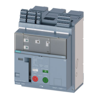
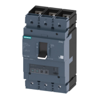
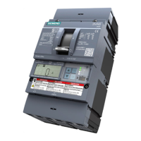
3VF circuit-breaker with internal accessories (alarm switch, auxiliary switch) and motorized
operating mechanism
Note: The motorized operating mechanism is needed for remote control of the circuit-breaker. If this
is not fitted, the circuit-breaker cannot be switched ON and OFF via PROFIBUS. The measurement
and warning functions are operational, however.
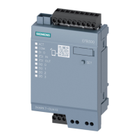
Suitable SIMOCODE-DP basic unit (cf. Selection table, page 17)
Connecting cable for parameterization using a PC or notebook
Diskette with type or GSD file (supplied with SIMOCODE-DP manual)
Parameter file (included in Win-SIMOCODE-DP from 6/98)
Win-SIMOCODE-DP software or 3WX36 handheld operator panel
COM-PROFIBUS software, only required for parameterization via PROFIBUS-DP
2.) Check the system requirements
The second step involves checking the following requirements for connecting 3VF to PROFIBUS-DP:
The 3VF circuit-breaker must be installed and wired in accordance with the circuit diagram on
pages 14/15.
The PROFIBUS-DP master must be present and operational.
SIMOCODE-DP must be correctly configured and installed (cf. user guide).
3.) Connect SIMOCODE-DP to PROFIBUS-DP
The bus cable can be connected to the SIMOCODE-DP 9-pin SUB-D connector using the standard
PROFIBUS-DP connector (order no. 6ES7972-0B.10), or it can be connected directly to the screw
terminals labeled "PROFIBUS-DP".

 Loading...