181/327
Building Technologies Basic Documentation LMV5... CC1P7550en
9 Commissioning instructions for the LMV5 22.05.2018
9.4 Extra functions of the LMV5
Menu level 1 Menu level 2 Menu level 3 Menu level 4 Menu level 5 Menu level 6
Params & Display
BurnerControl
ValveProving
ValveProvingType
Config_PS-VP/CPI
VP_EvacTme
VP_TmeAtmPress
VP_FillTme
VP_Tme_GasPress
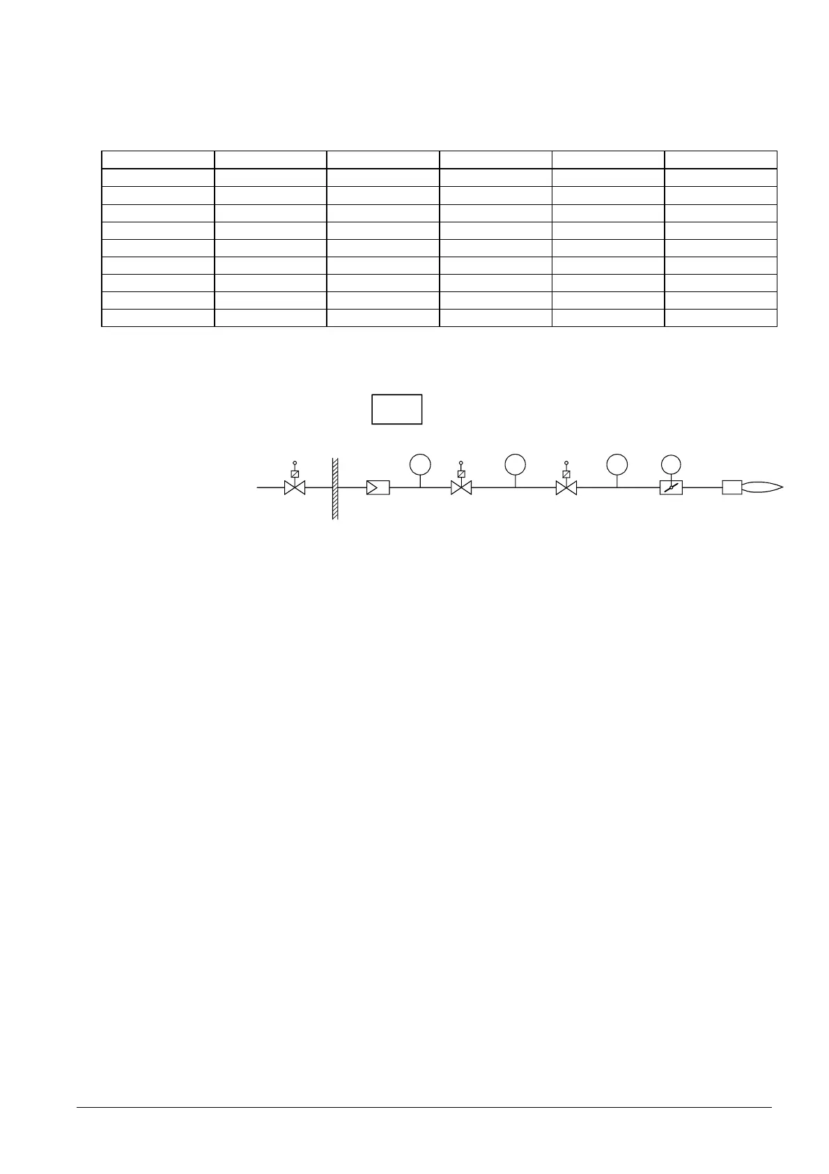
The gas volume contained in the piping between the valves (including the valve
volume) must be calculated in accordance with the type of gas train.
SV
V1 V2
Direct ignition
G
Program
7550s 01E/0 202
ACT
PS
max
PS
min
PS
VP
Figure 83: Extra functions of the LMV5
Determination of the test time with predefined leakage rate to be detected during
valve proving:
(P
G
- P
w
) • V • 3600
t
Test
=
atm
•
Leck
Determination of the detected leakage rate during valve proving:
(P
G
- P
w
) • V • 3600
Q
Leck
=
atm
•
Test
Q
Leck
in l/h Leakage rate in liters per hour
P
G
in mbar Overpressure between the valves at the beginning of the test phase
P
W
in mbar Overpressure set on the pressure switch (normally 50% of the
gas inlet pressure)
P
atm
in mbar Absolute air pressure (1,013 mbar normal pressure)
V in l Volume between the valves (test volume)
including valve volume and pilot path (Gp1) if present
t
Test
in s Test time
27. Valve leak test (valve
proving)
Example of fuel train
Legend
 Loading...

