237/327
Building Technologies Basic Documentation LMV5... CC1P7550en
17 Block diagram of contact links 22.05.2018
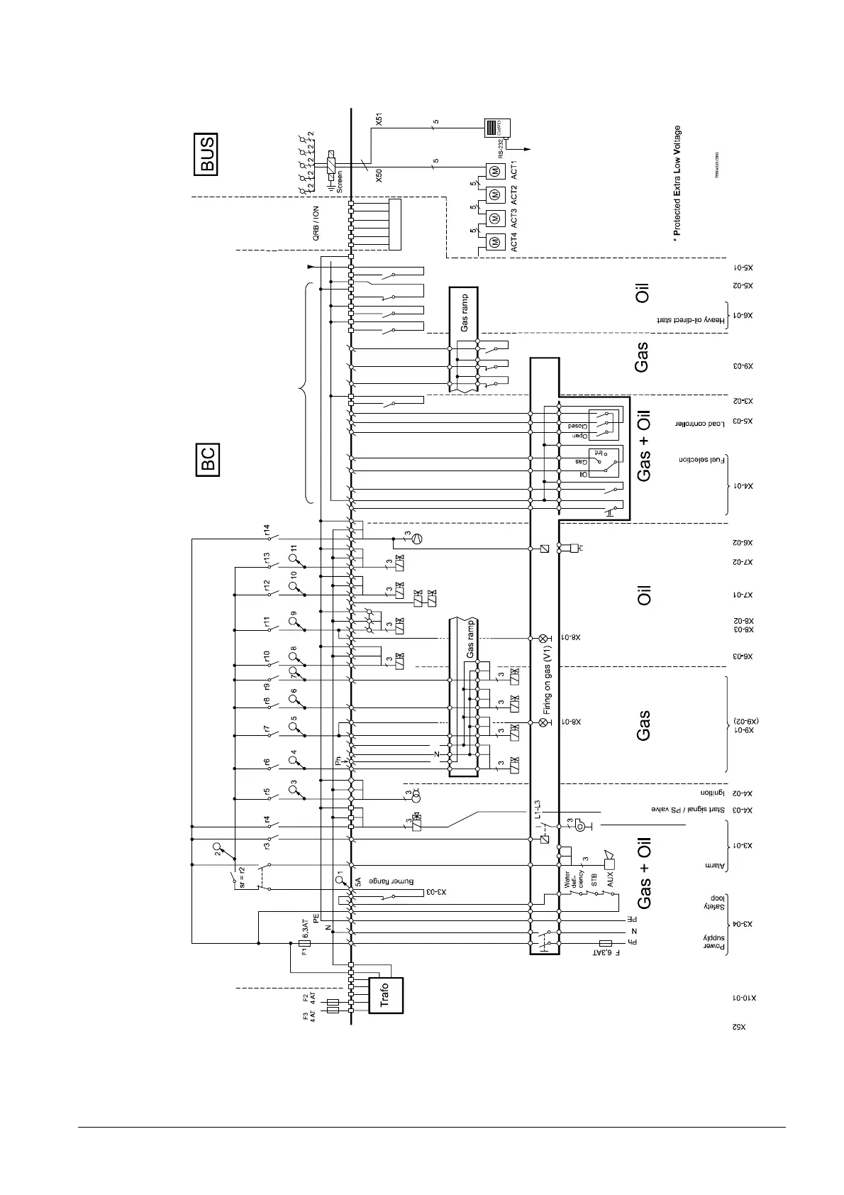
17 Block diagram of contact links
Firing on oil (V1)
Extern
Mains
SV
Fan
V 1
PV
V 2
2 x 115 V
al = r1
Pressure switch - VP / or CPI
Fan contactor contact
or / FGR-PS
Pressure switch min.
Pressure switch max.
Pressure switch min./
release of startup
Release of startup
Pressure switch max.
external
Magnetic clutc
Reset
Air pressure switch (A
O N/O FF
Ph AC 230 V
Inputs
Fla
a
PELV*
V 3
V 2
V 1
SV or preheater startup with heavy oil
P
Air damper
Gas damper
Oil pressure controller
Mixing device
Display and
operation
PELV*
P
Figure 110: Block diagram of contact links for LMV5
 Loading...

