34/327
Building Technologies Basic Documentation LMV5... CC1P7550en
4 Burner control 22.05.2018
4.1.1.3 QRI (suited for continuous operation)
Supply voltage operation / test at terminal
POWER QRI (X10–02 pin 2)
Approx. DC 14 / 21 V
Required signal voltage at terminal FSV /
QRI (X10–02 pin 6)
Min. DC 3.5 V
Display flame approx. 50%
(with factory setting of the parameter
StandardFactor)
Permissible signal voltage during
extraneous light test
Max. DC 0,3 V
Possible signal voltage terminal flame
signal amplifier / QRI (X10-02 pin 6)
Max. DC 5,5 V
Display flame approx. 100%
(with factory setting of the parameter
StandardFactor)
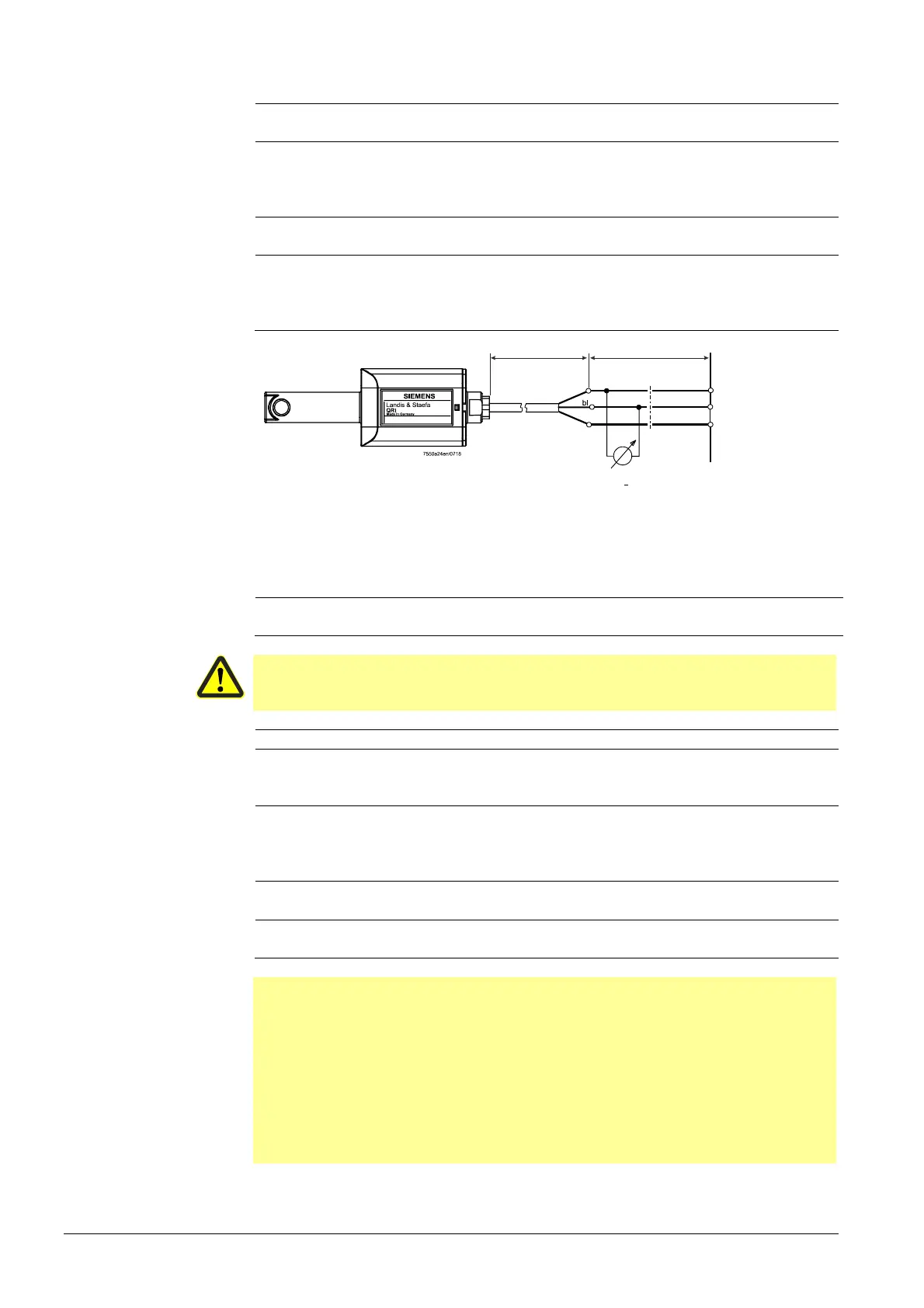
br
0...10 V
X10-02 / 4 N
Power supply a
LMV...
+
sw
Figure 25: Connection diagram QRI
For detailed information, refer to Data Sheet N7719.
4.1.1.4 Ionization (suited for continuous operation)
No-load voltage at terminal ION (X10–03
pin 1)
Approx. UMains
Caution!
The ionization probe must be installed such that protection against electrical
shock is ensured!
Short-circuit current Max. AC 0.5 mA
Required detector current Min. DC 6 µA, display flame approx. 50%
(at factory setting of StandardFactor)
parameter)
Possible detector current Max. DC 85 µA, display flame approx.
100%
(at factory setting of StandardFactor)
parameter)
Permissible detector current during
extraneous light test
Max. DC 0,3 µA
Permissible length of detector cable
(laid separately)
100 m (wire-earth 100 pF/m)
Β
Note!
The greater the detector cable capacitance (cable length), the lower the voltage at the
ionization probe and, therefore, the lower the detector current. In the case of extensive
cable lengths and high-resistance flames, it may be necessary to use low-capacitance
cables (e.g. ignition cable).
The electronic circuit is designed such that impacts of the ignition spark on the
ionization current are largely eliminated. Nevertheless, it must be ensured that the
minimum detector current required will already be reached during the ignition phase.
If that is not the case, the connections of the ignition transformer on the primary side
must be changed and/or the location of the electrodes also.
Connection diagram
 Loading...

