250/327
Building Technologies Basic Documentation LMV5... CC1P7550en
18 VSD module 17.10.2012
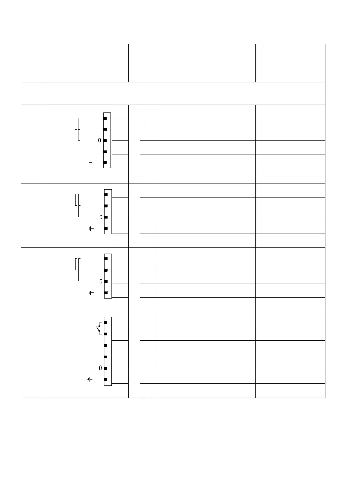
18.4 Description of connection terminals for the
VSD module
Terminal
marking
Connection symbol
Safety class
Input
Output
Description of connection Electrical rating
VSD module
X70
FE
Usensor
Pulse-IN
Reserve
2 Wire
PIN 1
III
˜ Power supply for speed sensor
Approx. 10 V
Max. 45 mA
PIN 2
˜ Speed input
Uin max = DC 10 V
Uin min High level = DC 3 V
Uin max Low level = DC 1.5 V
PIN 3
˜ Reference ground
PIN 4
Reserve
PIN 5
˜ Functional earth for shield connection
X71
Usensor
FE
2 Wire
Pulse-IN
PIN 1
III
˜ Power supply for fuel meter
Approx. 10 V
Max. 45 mA
PIN 2
˜ Fuel meter input gas
Uin max = DC 10 V
Uin min High level = DC 3 V
Uin max Low level = DC 1.5 V
PIN 3
˜ Reference ground
PIN 4
˜ Functional earth for shield connection
X72
Usensor
FE
2 Wire
Pulse-IN
PIN 1
III
˜ Power supply for fuel meter
Approx. 10 V
Max. 45 mA
PIN 2
˜ Fuel meter input oil
Uin max = DC 10 V
Uin min High level = DC 3 V
Uin max Low level = DC 1.5 V
PIN 3
˜ Reference ground
PIN 4
˜ Functional earth for shield connection
X73
Start - OUT
12-24VDC Alarm-IN
0/4-20mA Setpoint OUT
FE
PIN 1
III
˜ Reference contact
Max. AC / DC 24 V,
Max. 2 A
PIN 2
˜ Release contact
PIN 3
˜ Alarm input DC 0...24 V
PIN 4
˜ 0 / 4...20 mA control of VSD
0...20 mA
RLmax = 750 ς
PIN 5
˜ Reference ground
PIN 6
˜ Functional earth
 Loading...

