2 Using the MJ-4A & MJ-4B Operator Panel and Controls
14 Siemens Energy, Inc.
2.9 Local Data Port
The Local Data Port on the front panel supports connec-
tion to a PC or other communications device. It transfers
data in either direction: the MJ-4
Control Panel can provide
meter and status information to an external device, and
the control program can be configured from an external
device.
The Local Data Port supports data transmission at stan-
dard data rates from 300 to 19200 baud, inclusive, using
the 2200 communications protocol enhanced with MJ-4
data fields.
The physical interface is a standard 9-pin D-type subminia-
ture connector.
The pinouts match the PC-AT™ RS-232 port connector
(see Table 2.4):
* indicates factory default settings.
Normally, only pins 2, 3, and 5 are needed to communi-
cate through the Data Port.
When using a straight-through cable, the Local Data port
should be jumpered as “DCE” for connection to a terminal
device (such as a notebook or laptop computer); and as
“DTE” for connection to a modem. By default, the Local
Data Port is jumpered as DCE.
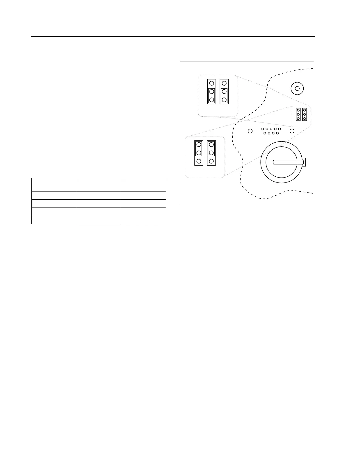
Figure 2.4 shows the jumper location for the Data Port
connections.
The device used for communications must be configured
to match the following Data Port items in the <COMMU-
NICATIONS> Menu.
•DatPortBaud
• Data Parity
• DataPortAddr - If addressing is on, use the Comm
Addr parameter as the Data Port address.
Figure 2.5 Data Port Jumper Locations
The MJ-4 jumpers on the main circuit board are internal.
See Appendix J for procedure.
See Appendix J for other jumper locations and default set-
tings.
When repositioning jumpers, use proper Electro-Static
Discharge (ESD) precautions. If possible, use an ESD
wrist strap. If no wrist strap is available, touch a grounded
surface before beginning. (Two accessible ground points
are the screw jacks of the Data Port connector.)
Table 2.4 Local Data Port Pinouts
Signal
Description
“DTE” Pin
Number(s)
“DCE” Pin
Number(s)*
MJ-4
output 3 2
MJ-4 Input 2 3
Signal Ground 5 5
DCD, DSR, CTS ) -- (no connection) -- (no connection)
J22
J22
J22
J23
J23
J23
BT1
1
1
1
1
1
1
2
2
2
2
2
2
3
3
3
3
3
3
Jumpered for DTE
Jumpered for DCE
 Loading...


