Appendix K: Terminal Strip Connections
78 Siemens Energy, Inc.
K Terminal Strip Connections
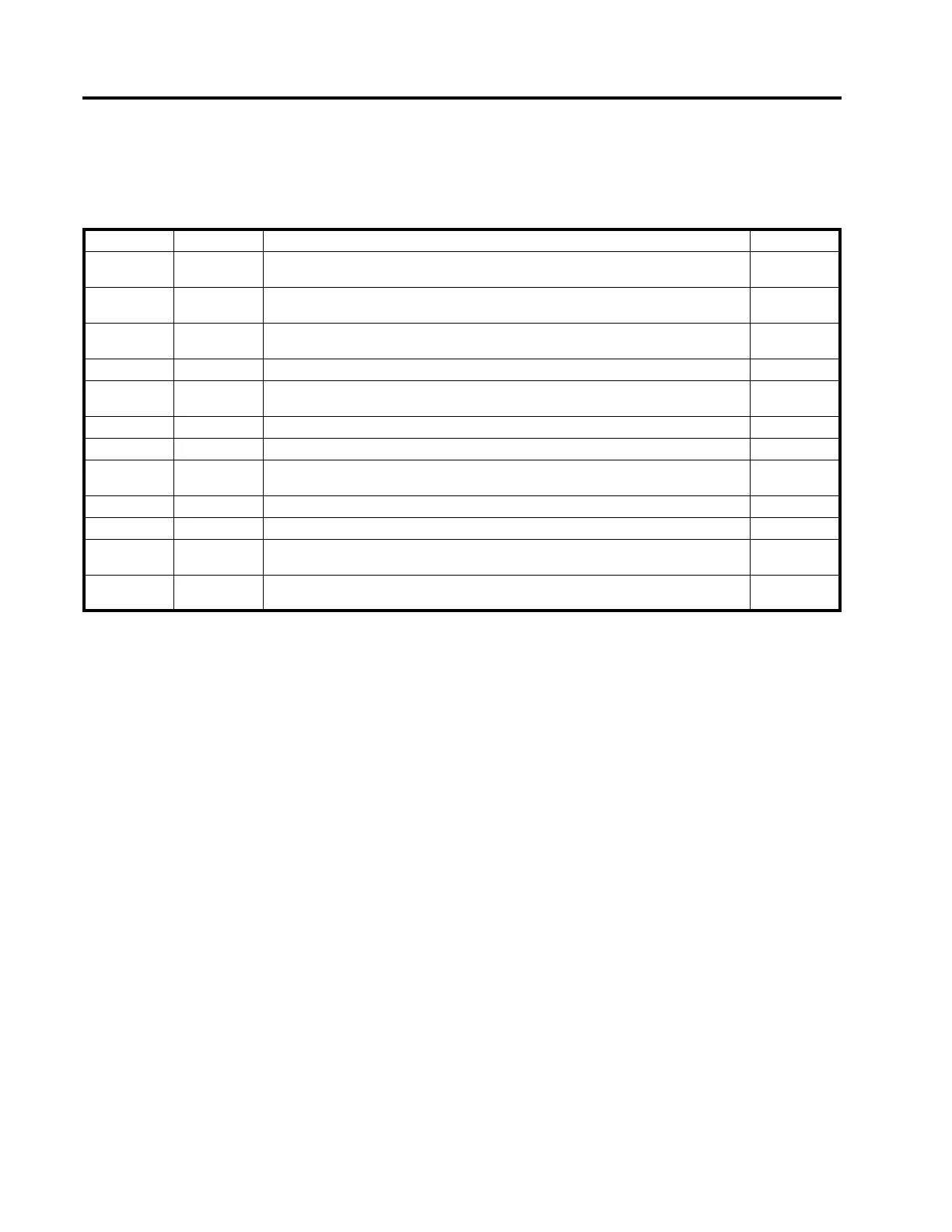
Table K.1 below describes the connections for terminal strip P2A.
* indicates standard "Polarized Disconnect Switch (PDS)" signals. For Siemens regulators, these ten signals connect to the
corresponding pins of the PDS connector block.
Table K.1 Connections for Terminal Strip P2A
Pin Number Signal Name Description I/O / Power
1 HS For Cooper Regulators Only. "Hold Switch" connection. Applies power to tap changer
to complete tap change after "Hold Switch" contact makes.
Power
2 U112 For Cooper Regulators Only. Neutral Position Indication. When closed to AC hot, indi-
cates tap changer is in neutral position. Turns on Neutralite.
Input
3 U12* High side of neutral position indicator. When closed to AC ground ("E"), indicates tap
changer is in neutral position. Turns on Neutralite.
Input
4 P2* Potential Transformer output (if present). Power/Sense
5 C2* High side of Current Transformer. [C2 terminal at P3B-12 is normally externally jum-
pered to C at P3B-11.]
Input
6 E* Neutral return for Control Panel, PT, and Utility winding. Chassis ground. Ground
7 E1* Low side of Current Transformer. Ground
8 U2* High side of Utility (Tertiary) winding. Control Panel derives "Normal" power from this
signal. Provides voltage phase reference for power flow direction.
Power/Sense
9 J* Terminal J - Tap Changer Motor Raise signal. Output
10 K* Terminal K - Tap Changer Motor Lower signal. Output
11 U10* High side of Operation Counter switch. Closes to E. Indicates when a tap change has
occurred.
Input
12 U11* High side of Regulator Drag Hands Reset solenoid. Returns to E. Used to reset the
drag hands of the Tap Position Dial mounted on the regulator.
Output
 Loading...


