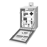
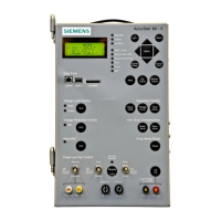
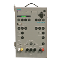
8 MJ-4A & MJ-4B Control Panel Basic Troubleshooting
Siemens Energy, Inc. 55
8 MJ-4A & MJ-4B Control Panel Basic Troubleshooting
8.1 Introduction
MJ-4
Control Panel service is primarily accomplished at
the factory. However, certain basic procedures can be
accomplished in the field. This chapter outlines a set of
procedures whose major objectives are to:
1. Ensure that the fault is inside the MJ-4
(and not in
external connections or connected equipment).
2. Ensure that the fault is not due to improper jumper
arrangements or some other user-correctable condi-
tion.
3. Determine whether the fault can be locally repaired
(e.g., by replacing a fuse).
Troubleshooting approaches depend upon the problem.
Among other indicators, you should consider:
• Visual review of the unit.
• Alerts (see Table 8.1 below).
8.2 Visual Inspection
Check:
• Power and Sensing fuses
• External Source fuse (if External Source Terminals are
used to power the unit)
• Fuse connectors not mated properly
• Jumpers not in their correct positions
• Terminal Strip connectors not mated properly
• Terminal Strip connector jumpers missing or screws
not tightened properly
CAUTION
120 volts on terminal block, leads,
and inside control panel housing.
Disconnect all power sources before
making connections to the terminal block
or opening the control panel housing.
May result in minor or moderate injury
including equipment damage.
Table 8.1 Alert Messages
Alert Name What to Check
Low Current Check E1 and C2 wiring. Check calibration on the Current inputs.
Auto Inhibit This alert does not indicate a fault condition. It indicates that Automatic Inhibit has been activated (either via the
communications link or via the Automatic Inhibit Input terminals
Tap Track Error May indicate a temporary fault condition (failure to detect a transition on one of several input lines.) Check PDS sig-
nals J, K, U10 and U12.
Neutral Sig. Err May indicate a temporary fault condition (failure to detect a transition on one of several input lines.) This alert could
also indicate a problem with the Neutralite
™ input signal. Check the Neutral (PDS-U12) input.
Tap Pos ???? May indicate a temporary fault condition (failure to detect a transition within the allowed time period on one of sev-
eral input lines.) Check the Neutral (PDS-U12) and Operations Counter (PDS-U10) inputs.
Low PT Thresh This alert does not necessarily indicate an MJ-4
fault condition. Check to see whether this alert condition goes
away when both U2 and P2 are above the PT Threshold.
Overcurrent This alert does not (normally) indicate an MJ-4
fault condition. Ensure that this Alert goes away when an in-range
current (0-200 mA) is applied at C2/E1.
NV RAM Reset May indicate a temporary fault condition. If condition appears repeatedly, replace the unit.
Low Battery Indicates that it is time to replace the Lithium Battery. If condition persists after a good battery is installed, check
that the battery was installed properly. If fault persists, consult the factory.
High Voltage May indicate a temporary system fault condition. If condition persists when in-range voltages (90-140 VAC) are
applied to both PDS-U2 and PDS-P2 inputs, perform calibration.
Not in Auto Indicates that Remote-Auto/Off/Manual switch is in Manual.
R Limit Reached,
L Limit Reached
These alerts indicate that the tap position has reached or exceeded the pre-set threshold. These alerts may occur
during normal operation due to system conditions. If these alerts occur when system conditions do not warrant it,
their occurrence could indicate an MJ-4
failure. Verify the MJ-4
can automatically raise and lower tap position.
Self Test Fault This alert indicates a failure of one or more MJ-4
self tests. Consult your Siemens representative for instructions.

 Loading...
